Ordering details, Connections – ABUS Technologies SPI Smart Programmable Isolator User Manual
Page 6
ABUS TECHNOLOGIES INC.
6
Smart
Isolator
4. ORDERING DETAILS
TYPE
DESCRIPTION
Product SPI
Smart Programmable Isolator
Channel
S
Single Input
1 Input
D
Double Input
2 Input
Input
Type
L
Linear Signal such as, 4~20mA, 0~10V
T
Thermocouple or RTD
First
Output
B1
4 – 20 mA
B2
1 – 5 V
B3
0 – 10 mA
B4
0 – 5 V
Second
Output
C1
4 – 20 mA
C2
1 – 5 V
C3
0 – 10 mA
C4
0 – 5 V
Third
Output
D1
4 – 20 mA
D2
1 – 5 V
D3
0 – 10 mA
D4
0 – 5 V
N
None
Power
Supply
D
24 VDC
A
220 VAC
Example: SPI > S > L > B1 > C1 > N > A
Illustration:
1. Single circuit input at most correspondingly has four output;
2. Types of input and output signals can be selected;
3. Frequency signals can be input and output.
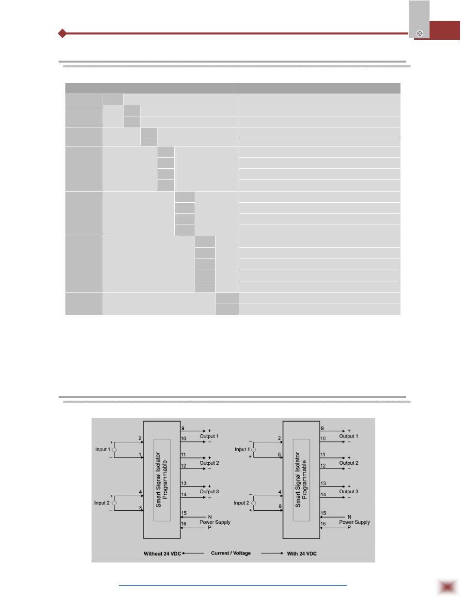
5. CONNECTIONS
Connection Diagram: Current & Voltage