Installation – ABUS Technologies DPSENSE-V Series Multi-Range Air Velocity Transmitter User Manual
Page 7
ABUS TECHNOLOGIES INC.
7
DPSense
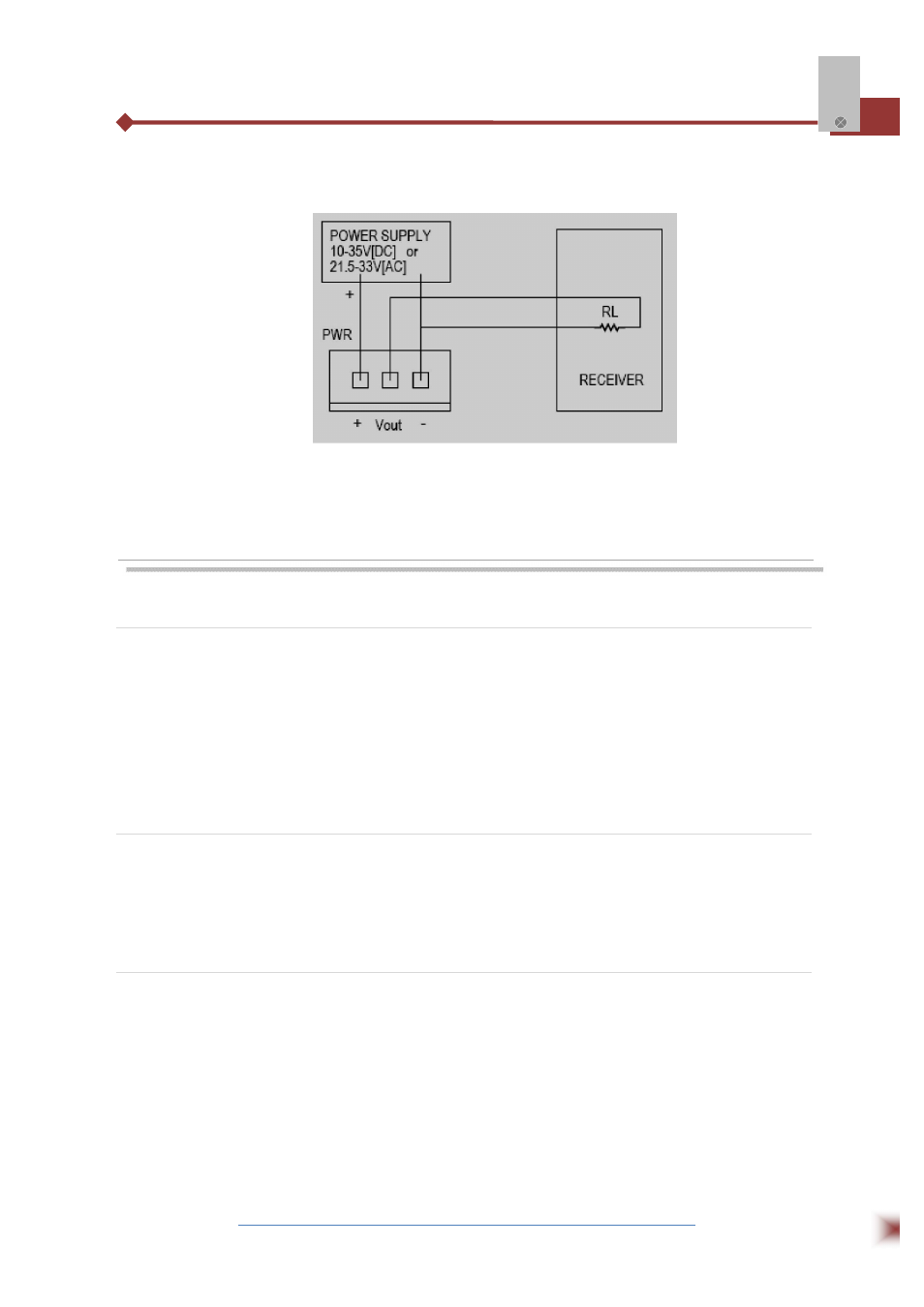
The output of Volt on PWR is 0-10 VDC, carrying no higher than 10 mA current and so against no lower
than 1
KΩ of the receiver load resistance.
NOTE: THE VOLTAGE FOR THE POWER MUST NOT BE HIGHER THAN THE RATED ONE, OR THE
TRANSMITTER WILL BE DAMAGED FOREVER.THEN THE TRANSMITTER WILL NOT BE
PREPARED FOR FREE.
6. INSTALLATION
6.1 Recommendation
•
Upon receipt please inspect the instrument for the intended application pressure range.
•
Install the instrument in a location away from fans, corners, heating and cooling coils
and other
equipment.
•
All standard DPSENSE-V transmitters are calibrated in the vertical position. To maintain the
specified accuracy, the transmitters must be mounted in the vertical surface
•
Make sure that the pressure ports and the electrical cable connecters are directed down in a
vertical position.
6.2 Mounting
Secure the transmitter on the vertical mounting surface with 4 provided screws, do not screw
down badly. Opening: the cover should be removed before the electrical connections are made. Contra-
rotate the cover until the ears of the cover have come to the other sides of the holes (observe the four
rectangle holes in the house), then remove the cover using fingers.
6.3 LCD Installation (Optional)
Any non display DPSENSE-V can get the display function by directly mounting the LCD display
on the main PCB board by the connecters CN1 and CN2. The kit contains an LCD display and
displacement cover with the LCD window (non display DPSENSE-V has no this window). The optional
LCD can display differential pressures (the unit and range displayed in the LCD are corresponding to
the relevant setup). After upgraded with the display kit, in case that the display value of the transmitter is
different from the analog output because of the incorrect adjustment by the user before upgrading,
calibrate the analog output’s zero to either 0 V or 4mA,the full scale to either 10V or 20 mA. See the
user calibration section for details on how to perform these operations. Most of the sectors below are
based on the DPSENSE-V with LCD display.