Electrical connections – ABUS Technologies DPSENSE-V Series Multi-Range Air Velocity Transmitter User Manual
Page 6
ABUS TECHNOLOGIES INC.
6
DPSense
5. ELECTRICAL CONNECTIONS
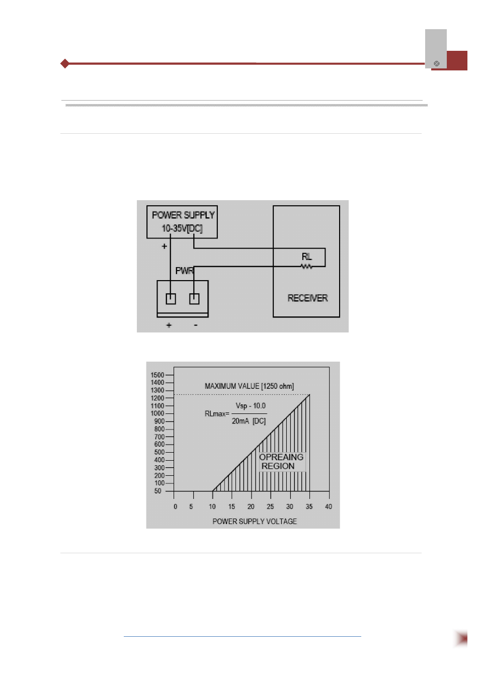
5.1 2-Wire Connections
A couple of terminal blocks PWR that connect the transmitter to the power and receiver are
located on the bottom of the PCB board. The polarities are signed by “+”and “-”. Make sure that the
connections between transmitter, power and receiver are correct according to Fig. below
The receiver load resistance (RL) for DDC/PLC/DCS can be got from the formula and graph in
fig. below.
5.2 3-Wire Connections
Three terminal blocks PWR that connect the transmitter to the power and receiver are located
on the bottom of the PCB board. The polarities are signed by “+”and “-”, and the output as Volt. Make
sure that the connections between transmitter, power and receiver are correct according to Fig. below.