User operation guide, Ir pass-through – ABtUS MAX-HDMI816A-G User Manual
Page 2
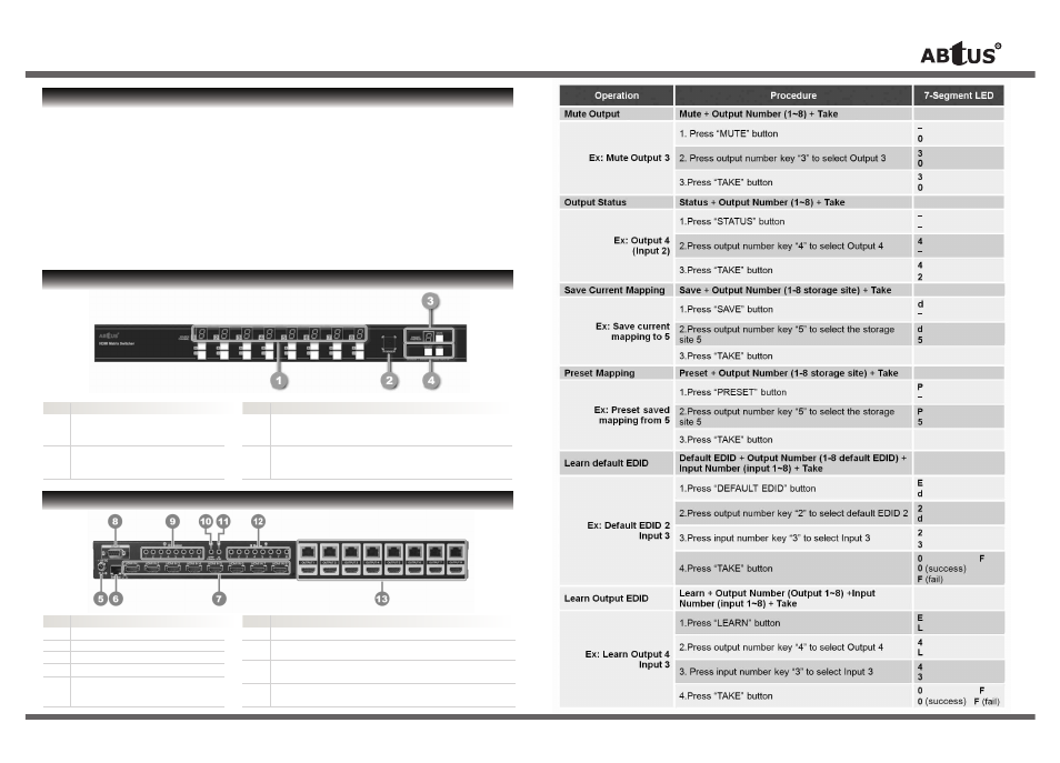
User Operation Guide
* Specifications are subject to changes without notice.
FRONT PANEL OVERVIEW
** For detail, updated Command Code and Application Software, please visit and download from www.abtussingapore.com
PRODUCT HIGHLIGHTS
•
Support HDMI Deep Color & full 3D
•
HDCP compliant
•
Allows any source to be displayed on multiple displays at the same time
•
Allows any HDMI display to view any HDMI source at any time
•
Supports 7.1 channel digital audio
•
Supports default HDMI EDID and learns the EDID of displays
•
Bi-directional IR path
•
Supports IR, RS-232 and ethernet control
•
Extends video signal up to 35m (115 feet) over single CAT-5 at 1080p
•
Easy installation with rack-mounting and wall-mounting designs for transmitter and
receiver respectively
•
Fast response time – 2~5 seconds for channel switch
5.
+12V DC: 12DC power jack
6.
Ethernet: Ethernet control port
7.
INPUT 1-8: HDMI inputs
8.
RS-232: RS-232 control port
9.
IR Receiver 1-8:
Infrared 3.5mm socket for plugging in
the extension cable of IR receiver
Item Description
10. System IR Receiver: Ext. IR Receiver
11. All IR Output:
3.5mm IR blaster socket for HDMI source control on all 8 inputs
12.
IR Blaster 1-8:
3.5mm IR blaster socket for individual HDMI source control
13.
Output Port 1-8:
RJ-45 & local loop out HDMI outputs for each output channel
Item Description
FRONT PANEL
REAR PANEL
1.
Signal Level: Adjust the 8-level equalization control used to adjust the received HDMI signals.The HDMI
signal level varies from MAX (strongest) to MIN (weakest) for respective transmission length from longest
possible range to a shorter distance. Please adjust the signal level from MIN to MAX and stop whenever
the audio/video is playing normally. Inappropriate signal level setting may cause overpowering issue which
would shorten the product life significantly!
2.
HDMI Out: Connect to a HDMI display with a HDMI male to male cable
3.
IR Receiver: Infrared 3.5mm socket for plugging in the extension cable of IR receiver
4.
IR Blaster: Infrared 3.5mm socket for plugging in the extension cable of IR blaster
5.
+5V DC: Connect to 5V DC power supply
6.
HDMI Signal IN: Plug in a Cat-6 shielded cable that needs to be linked to the transmitting unit
MAX-HDMI816A-G
Item
Description
> IR PASS-THROUGH
IR BLASTER
IR RECEIVER
MAX-HDMI816A-G
ALL IR OUT:
The default location for IR blaster to transmit all IR command signals received from any of
the four remote receivers to all of the HDMI sources.
IR BLASTER 1-8: IR blaster connected here can only transmit IR command signals from the remote receivers
that are setting at respective input channel from 1 to 4.
SYSTEM IR:
Receives IR commands from remote control.
IR RECEIVER 1-4: Receives IR commands from individual remote control.
CAT-HDMI11RA-G
IR BLASTER:
IR control on individual display device.
IR RECEIVER:
IR receiver connected here can receive all IR command signals from the IR remote controls
of MAX-HDMI816A-G and all other HDMI source devices.
IR Extenders
IR Sockets
Incorrect placement of IR Blaster and Receiver may result in the failure of the IR extenders. Please check carefully
before plugging in the IR extender to the respective IR sockets. Damages arising from this would not be covered
under warranty.
CAUTION:
1.
Source Status:
Input source indicator LED
3.
Output Push Button & 7-Segment LED:
Item Description
2.
IR Sensor:
IR sensor for receiving the
IR commands from IR remote
Front panel push buttons used to select the number of
input source & LED display for input channels
Item Description
Front panel push buttons used to select the number of display
channel & LED display for output ports
4.
Input Push Button & 7-Segment LED:
Transmitting unit > MAX-HDMI816A-G
Receiving unit > CAT-HDMI11RA-G
REAR PANEL OVERVIEW
User Operation Guide
** For detail, updated Command Code and Application Software, please visit and download from www.abtussingapore.com
HARDWARE INSTALLATION
3. Preset Mapping Mode
1) Keep pushing “output- (preset)” button until the output LED shows “P” to enter the Preset Mapping Mode.
2) Use the “+”or “-” input push button to select the saved mapping configuration (1~8) which you want to recall
3) After you select the desired mapping configuration number, the LED will blink twice & the mapping setting will be effective
4) If you push the “output+ (save)” button before the mapping setting is effective, the LED will show
to quit the Preset Mapping Mode
4. Default EDID Mode
1) Push “input+ (default)” button to select the input channel which you want to learn default EDID and then
keep pushing “input+ (default)” button when you select your desired input channel
2) Push the “+”or “-” output push button and then the LED will show “E” “d” one time to enter Learn Default
EDID Mode
3) Use “+”or “-” output push button to select the default EDID mode (1~8)
4) Release “input+ (default)” button after selecting the desired default EDID mode, and then the LED will
blink twice and the setting will be effective
5) It will quit the Learn Default EDID Mode if you push the “input- (learn)” button before the setting is effective
6) The LED will show “0” “0” if the setting is success
The LED will show “F” “F” if the setting is failure
5. EDID Learning Mode
1) Push “input- (learn)” button to select the input channel which you want to learn EDID from HDMI output
and then keep pushing “input- (learn)” button when you select your desired input channel
2) Push the “+”or “-” output push button and then the LED will show “E” “L” one time to enter Learn Output EDID Mode
3) Use “+”or “-” output push button to select the output port number
4) Release “input- (learn)” button after selecting the desired output port number, and then the LED will
blink twice and the setting will be effective
5) It will quit the Learn Output EDID Mode if you push the “input+ (default)” button before the setting is effective
6) The LED will show “0” “0” if the setting is success, The LED will show “F” “F” if the setting is failure
1. IN/OUT Switch
3
-
1. Press output number key “3” to select Output 3
3
2
2. Press input number key “2” to select Input 2
Ex: Input 2
To Output 3
Operation
Procedure
7-Segment LED
IN/OUT Switch
Output Number (1~8) + Input Number (1~8)
2. Function Key
Button
Function
OFF
Standby mode
ON
Power on the matrix switcher
MUTE
Turn off output’s video and audio
STATUS
Preset output status
SAVE
Save current mapping mode
PRESET
Preset mapping mode
DEFAULT EDID
Begin default EDID selection
LEARN EDID
Begin EDID learning from one output
CLEAR
Clear the previous IR operation procedure
TAKE
Trigger the previous setting
F1
Reserved
F2
Reserved
Method B: IR Remote Control
Ex: