MIPRO ma101a User Manual
Page 6
6. ACT BUTTON:
(1)
Press the"ACT" button (13)onthecontrol panel of t h e MA-101aonce and the
numericLEDwill flash. Now "ACT"function is activated andreadyto program the
transmitter.
(2)
Positionthe "ACT" markingof thetransmitterwithin 30cm (12" of the ACTport (12)
facingtowards the"ACT" button (13) on the receiver as illustratedin thefigure below .
(3)
The ACTfunction willbe deactivated automatically once thetransmitterfrequency is
locked on andnumeric LEDstopsflashing.
7. SPECIFICATIONS:
T.H.D.
Dimensions (m/m)
Approvals& Patents
Note
MA-101a
PLL
27W(RMS)/4Ω
(load)
50Hz-15KHz
3dB
±
UHF 600~950MHz
40KHz
Variousspecifications oncarrierfrequency ranges,maximum
deviations and RFoutputpowercomplywiththeregulations of
different countries.
8
9
1
2
3 4
5
6
7
9
8
Model
Spec
CarrierFrequencyRange
OscillationMode
Max.Deviation
Antenna
Sensitivity
Power Output
Frequency Response
Audio Input
Speaker
Power Supply
Charging Time
Operating Time
Weight
R X
Built I n
12/2.7AH rechargeable battery and intelligent charger
with90~260VAC adapter
Built-inwireless receiver, 1 / 4 " m i c a n d l i n e - i n j a c k s
285(L) x 1 6 0 ( W )
178(H)
x
8 hours talk time
Black
3 K g s (with battery)
Built-in 5 inch highsensitivity full range speaker
<1 %
6 d B m V a t S / N > 7 0 d B
ExteriorColors
Operation Mode
Direct operation on speaker unit
Wireless Portable PAAmplifier
Handheld Wireless Microphone
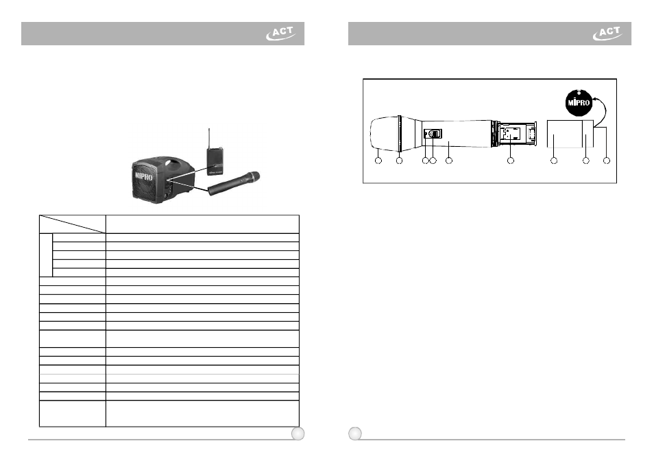
1. PARTS NAMES AND FUNCTIONS
(Fig.1)
1.
Grille: Protectscartridge, prevents "POP" noiseandprevents microphone
from rolling with polygonal shape.
2.
Color Ring: For frequency differentiation.
3.
Battery Status Indicator: Indicates power on / off and the battery status.
When the power switch is turned ON, the red LEDs indicator flashes
briefly, indicating normal battery status. If n o f l a s h occurs, it has either no
battery or the battery is discharged or installed incorrectly. If a fter power
on the indicator stays lighted, it warns that the battery i s w e a k and should
be replaced.
4.
Power On-off Switch: Slide the switch for power" ON " o r " O F F " .
5.
Housing:Upper portion to be connected to capsule moduleandbattery.
Internally, it holds transmitter PCB.
6.
Battery Compartment:Designedto accommodate one 9 Volt battery.
7.
Battery Cap: Covers battery in the battery compartment.
8.
Anti-roll R ing: Forfrequency differentiation.
9.
ACT Signal Receptor:ReceivingACTsignal and adjusting frequency
automatically.
Once the channel has been selectedonthereceiver,follow these steps to
program thetransmitter to the same frequency:
New style patents; Telecom and safetyregulations approved
4hours Automaticrechargeablebatterymanagement
(
)