MIPRO ma101a User Manual
Page 5
DCIN18V
LINEIN
L I N E O U T
CHARGE
O N
POWER
WIRELESSLEVEL
MIN
M A X
OFF
M A X
M I C I N L E V E L
SCAN
ACT
CHANNEL
D C I N 1 8 V
LINEIN
LINEOUT
CHARGE
O N
POWER
WIRELESSLEVEL
MIN
M A X
O F F
M A X
MICINLEVEL
SCAN
ACT
CHANNEL
D C I N 1 8 V
LINEIN
LINEOUT
CHARGE
O N
POWER
WIRELESSLEVEL
MIN
M A X
O F F
M A X
MICINLEVEL
SCAN
ACT
CHANNEL
DCIN18V
L I N E I N
L I N E O U T
C H A R G E
O N
POWER
WIRELESSLEVEL
MIN
M A X
OFF
M A X
M I C I N L E V E L
SCAN
ACT
CHANNEL
DCIN18V
LINEIN
L I N E O U T
CHARGE
O N
POWER
WIRELESSLEVEL
MIN
M A X
OFF
M A X
M I C I N L E V E L
SCAN
ACT
CHANNEL
DCIN18V
L I N E I N
L I N E O U T
C H A R G E
O N
POWER
WIRELESSLEVEL
MIN
M A X
OFF
M A X
M I C I N L E V E L
SCAN
ACT
CHANNEL
DCIN18V
L I N E I N
L I N E O U T
CHARGE
O N
POWER
WIRELESSLEVEL
MIN
M A X
OFF
M A X
M I C I N L E V E L
SCAN
ACT
CHANNEL
DCIN18V
L I N E I N
L I N E O U T
CHARGE
O N
POWER
WIRELESSLEVEL
MIN
M A X
OFF
M A X
M I C I N L E V E L
SCAN
ACT
CHANNEL
a)
a)
b )
b )
c )
c )
d)
d)
6
7
Wireless Portable PAAmplifier
Wireless Portable PA Amplifier
With proper careandcharging, itisunlikelythatitwillbenecessaryto
replacetheMA-101abatteryforsometime. However,thereisanaccesspanel
providedforthis purpose. Ifextendedperiodsofusearerequiredwithouttime to
recharge thebattery, youmay wishtohaveasecondbatteryfullychargedand
readytoinstallanduse oncetheexistingoneisdrained. Thebatteryis a
standard 12V/2.7Agel cell and isavailablefromMIPRO.
1.
Lay the PA system onaflatsurface.
2.
Press down on the twofasteners at thetopofbatterycompartment.The
compartment door will now swing down o n i t s h i n g e .
3.
Remove the interior rear panel of the battery compartment by sliding i t u p . Use
caution, as the battery may "spring" forwardwhen you release this panel.
Carefully remove thebattery.
4.
Insert a fully charged battery, observing the correct polarity. Thetwoterminals on
the battery should benear the top of the battery with theprinted side up. This
alignment corresponds with the springs and terminals insidetheunit.
5.
Press the battery into theunit,holding it firmly against the springs, while sliding
the rear panel back into space. This may require twohands.
6.
Close the battery compartment door. Lift uponthetwofastenersuntil they "click"
into place.
4. REPLACING THE MA-101a BATTERY
5. SWITCHABLE CHANNEL FUNCTIONS
1.
Functions:
2. HowToSelectaFrequency
(a)
ThissystemincorporatesadvancedPLLsynthesizedoscillatordesign. Itallows
theusertofreelyselectanyofthe16preprogrammedswitchablefrequencies.
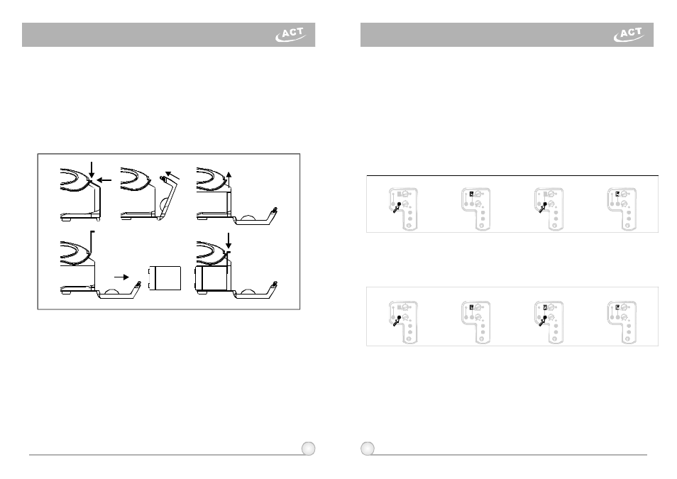
(a)
Auto-ScanningFrequencySet-up: Press andholdtheSCANbutton(14)for1
second. ReleasethebuttonwhennumericLED(11) flashes. Thenumeric
numberwillflashatotalof6times. ToactivatetheAutoScanfunction,pressthe
SCANbuttononcewithinthese6times. Aclearfrequencywillautomaticallybe
scannedandsaved/locked. *NotethattheAutoScanfunctionworksonlyduring
thenumericLEDflashing.
(b)
ManualFrequencySet-up: PressandholdtheSCANbutton(14)for1second.
ReleasethebuttonwhenthenumericLED(11)flashes. Thenumericnumber
willflashatotalof6times. Toselectanyofthe16frequenciesintheprogram,
pressandholdtheSCANbuttonuntilthedesiredfrequencyisdisplayed. This
frequencywillautomaticallybesaved/locked.
3. ChangeChannel When:
(a)
The existing channel is experiencinginterference or is otherwise
malfunctioning.
(b)
Selecting another channelformultiple system setup.
4. CautionsWhileChangingChannels:
(a)
When multiple MA-101a systems are needed to beused at the same
installation ascertain to set-up channel one unit at a time before proceed
with the second unit. Donotset-upchannels on all units simultaneously to
avoid existing channel interference.
(b)
When numeric LED reaches "_", it indicates an empty channel here.
Proceed until a numeric number appears.
Pressandhold"SCAN"button
for1second.
Pressandhold"SCAN"button
for1second.
LEDdisplayflashes.
LEDdisplayflashes.
Press"SCAN" buttonagainandrelease
willautoscanforanopenfrequency.
Press"SCAN"buttonandhold,
frequencywillchangeeverytwoflashes.
Whendoneitwillautosaved/locked.
Whendoneitwillautosaved/locked.