Nexen Linear Actuator 912732 User Manual
Page 5
FORM NO. L-21023-F-0812
5
LIMIT SWITCH ADJUSTMENT
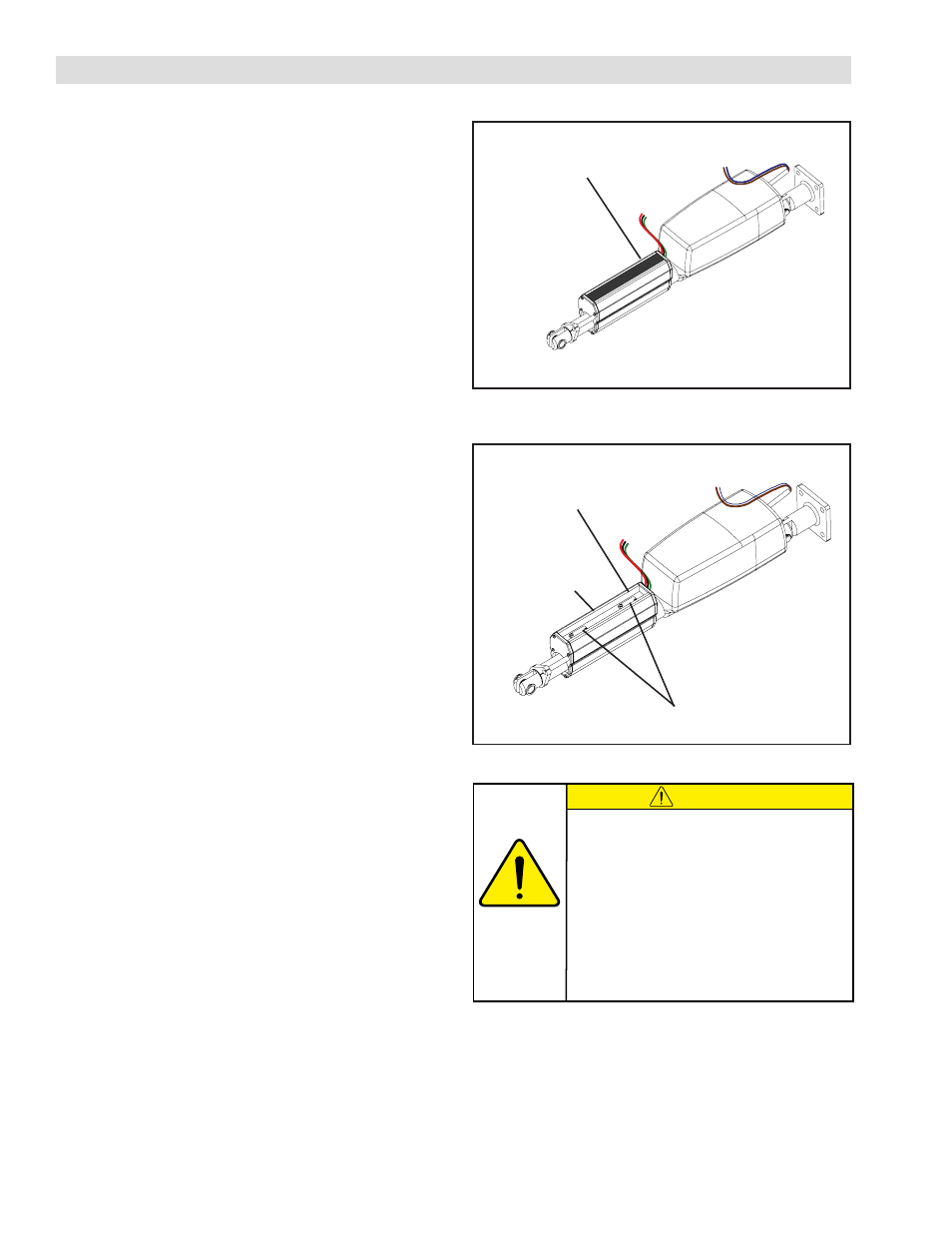
FIGURE 3
Rubber Sealing Strip
on Limit Switch Housing
FIGURE 4
Clamping Screw
Retraction
Limit Switch
Extension
Limit Switch
NOTE: Refer to Figures 3, 4
The limit switches factory default setting are for the maximum
stroke.
1. Turn the Web Guide Controller to "ON" and place it
in the manual mode.
2. Carefully remove the Rubber Sealing Strip from the
Limit Switch Housing.
3. Press the button on the Web Guide Controller that
extends the Linear Actuator until the desired extension
position is reached. Refer to your controller manual for
specific details.
4. Use a screwdriver to loosen the Clamping Screw on
the Extension Limit Switch.
5. Slide the Extension Limit Switch toward the Retraction
Switch until the Web Guide Controller indicates that
the switches have changed state.
6. Tighten the Clamping Screw on the Extension Limit
Switch.
7. Press the button on the Web Guide Controller that
retracts the Linear Actuator to the desired retraction
position. Refer to your controller manual for specific
details.
8. Use a screwdriver to loosen the Clamping Screw on
the Retraction Limit Switch.
9. Slide the Extension Limit Switch toward the Retraction
Switch until the Web Guide Controller indicates that
the switches have changed state.
10. Tighten the Clamping Screw on the Retraction Limit
Switch.
11. Replace the Rubber Sealing Strip in the Limit Switch
Housing.
CAUTION
If there is a physical obstruction or stop, then the
Limit Switches MUST be adjusted to interrupt
the Linear Actuator's movement before contact
is made with the physical obstruction or stop.
Failure to adjust the Limit Switches will damage
both the Linear Actuator and the Web Guiding
Mechanism.
If there is no physical obstruction to travel, then
the Limit Switches may be left in their factory set
default positions.