Introduction, Installation, Electrical connections – Nexen Linear Actuator 912732 User Manual
Page 4: Caution
4
FORM NO. L-21023-F-0812
INTRODUCTION
Nexen’s Linear Actuators provide the thrust that is required to move an unwind stand, a wind up roll stand or to convert an
existing hydraulically actuated web guiding mechanism to electrical actuation.
Nexen’s Linear Actuators are available in several models with different strokes.
To ensure optimum response and accuracy, roll stands should be mounted on linear ball bearings. Sliding ways and wheel
track systems have higher coefficients of friction which requires greater break away thrust. Greater break away thrust
prevents accurate, minute corrections.
INSTALLATION
NOTE: Refer to Figure 1
1. Attach the Mounting Base bracket to a fixed member
of the guiding mechanism.
2. Connect the Clevis End to the moveable member of
the guiding mechanism.
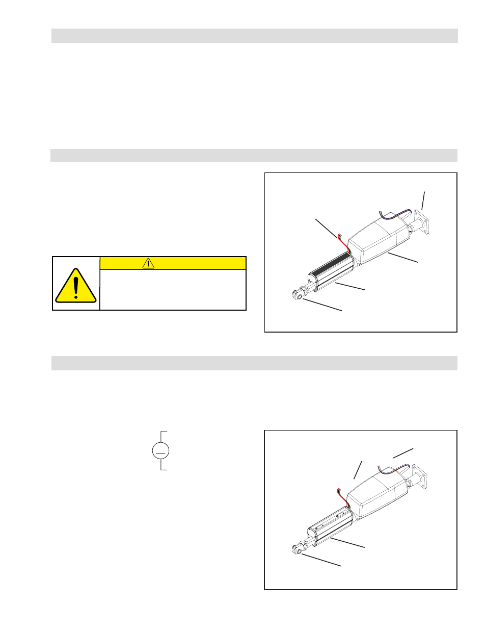
ELECTRICAL CONNECTIONS
FIGURE 1
Limit Switch Leads
Mounting Base
Motor
Limit Switch Housing
Clevis End
NOTE: Refer to Figure 2
1. Connect the motor leads of the Linear Actuator to the
motor output terminals of the Web Guide Controller,
as follows:
M
Brown
Blue
NOTE: If the Linear Actuator moves in the wrong
direction, then reverse the wire lead
connections.
2. Connect the Limit Switch leads to the Limit Switch
terminals of the Web Guide Controller as follows:
Red lead
to
Extension.
Black lead
to
Retraction.
Green lead
to
Common.
Shield lead
to
Shield.
CAUTION
Do NOT use the Linear Actuator for Radial
(side) loads.
The Linear Actuator is designed for axial
(thrust) loads ONLY.
FIGURE 2
Limit Switch Leads
Motor
Leads
Limit Switch Housing
Clevis End
Red
Blac
k
Green
Brown
Blue