Theory of operation, Installation – Nexen PH 16 912085 User Manual
Page 4
4
FORM NO. L-20140-G-0105
THEORY OF OPERATION
Nexen’s PH-16 and PH-21 are photo electric edge position
sensors, used as the sensing element of an Edge Position
Control (EPC) System. The sensor may be applied to either
side of the web, or two sensors may be used (one on each
side of the web), for Center Position Control (CPC).
Sensing is accomplished by a light emitting diode (LED), which
transmits light across a gap to a light sensing array. The
sensing array produces an electrical voltage directly
proportional to the amount of light received from the LED. As
an opaque web of material moves in and out of the gap, the
sensor output varies.
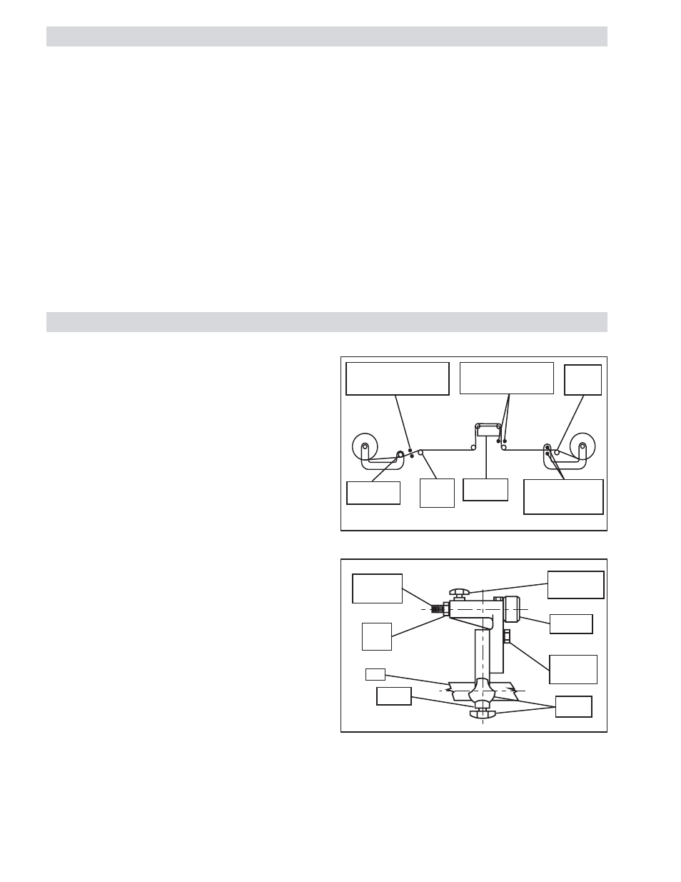
INSTALLATION
1.
Provide a 1 In. [25 mm] square bar which will span the
web (See Figure 1).
NOTE: This bar is used to support the mounting bracket.
2.
Install the Mounting Bracket on the bar (See Figure 2).
3.
Mount the bar to the machine (See Figure 1).
NOTE: Make sure the bar is rigidly mounted; any movement
of the bar will affect sensor position.
4.
Install a sensor on the Adjusting Screw Projection and
secure it with the Sensor Locking Nut (See Figure 2).
5.
Loosen the Adjusting Screw Locking Knob and position
the Adjustment Screw to the midpoint of its travel
(approximately 0.6 In. [15 mm]) (See Figure 2).
Install Support Bar
either side (Mid-Process)
Install Support Bar either side
(Unwind) Support Bar must be
part of Main Machine Frame
Last
Machine
Roll
Roll attached to
Unwind Stand
First
Machine
Roll
Guide Roll
Mechanism
Install Support Bar
either side (Rewind)
Support Bar must be
part of Rewind Stand
FIGURE 1
Bar
Sensor
Locking
Nut
Adjusting
Screw
Projection
Clamping
Screws
Hex
Adjustment
Screw
Adjustment
Screw
FIGURE 2
Excitation for the LED is provided by a Web Guide Amplifier.
The sensor's output return signal is fed back to the same
amplifier for closed loop control.
A mounting bracket, provided with the sensor, includes a micro
adjustment screw and lock nut. The adjustment screw allows
up to 0.79 In. [20 mm] of sensor movement without moving the
bracket.
Adjusting Screw
Locking Knob
Mounting
Bracket