Gerät in betrieb nehmen, Betrieb, Abmessungen in mm (") – Pilz PSS SB Passive Junction User Manual
Page 7: Commissioning the unit, Operation, Dimensions in mm ("), Mettre l’appareil en service, Utilisation, Dimensions en mm (")
- 7 -
96 (3.77")
48 (1.88")
72 (2.83)
IP67 Line X4
Shield
IP20
Line
X2
Shield
br-LO
W
wt-GND gn-HIGH
rd-VCC
Power X1
Power
X0
1
2
3
4
1 2 3 4 5
X3
Passive Junction
311059
0V
24V
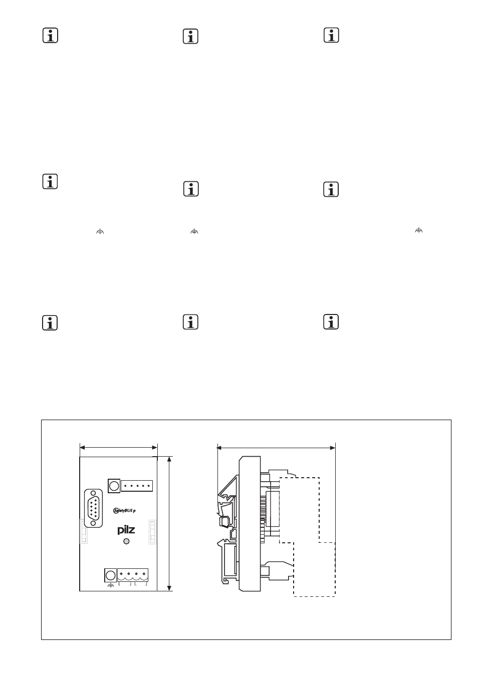
Fig. 6: Abmessungen mit SafetyBUS p-Stecker/Dimensions with SafetyBUS p connector/Abmessungen mit SafetyBUS p-Stecker
INFO
Beachten Sie die Angaben im Kapitel
"Installation und Montage" der
"SafetyBUS p Installationsrichtlinien".
IP20-Strang
Verbinden Sie den Kabelschirm einmal für
den gesamten Hauptstrang impedanzarm mit
der Schirmschiene oder Erdungsschiene
(Fig 1).
IP67-Strang
• Führen Sie den Kabelschirm des IP67-
Strangs auf einen der Anschlüsse der
beiden Klemmleisten X4 (SHIELD) oder
X3 (SHIELD).
INFO
Empfehlung: Legen Sie den Kabel-
schirm des IP67-Strangs an der
Klemme X3 (SHIELD) (siehe Fig. 2)
an.
• Verbinden Sie die Anschlüsse der
Klemmleiste X0 (
) impedanzarm mit der
Schirmschiene oder Erdungsschiene (Fig.
1).
• Beachten Sie die Angaben der Richtlinie
"SafetyBUS p - IP67 Physical Layer
Concept" des SafetyBUS p Club Interna-
tional e.V.
Gerät in Betrieb nehmen
INFO
Beachten Sie das Kapitel "Inbetrieb-
nahme" der "SafetyBUS p
Installationsrichtlinien".
Betrieb
Das Gerät ist betriebsbereit, wenn die LED
"POWER" dauerhaft leuchtet.
Abmessungen in mm (")
INFORMATION
Please refer to the information in the
chapter entitled "Installation and
Assembly" in the "SafetyBUS p
Installation Manual".
IP20 branch
Connect the shielded screening with low
impedance to the screen bar or earth bar;
this only needs to be done once for the
whole main branch (Fig 1).
IP67 branch
• Connect the cable shield of the IP67
branch to one of the connections on the
two terminal blocks X4 (SHIELD) or X3
(SHIELD).
INFORMATION
Recommendation: Connect the cable
shield of the IP67 branch to terminal
X3 (SHIELD) (see Fig. 2).
• Connect the X0 terminal block connections
( ) with low impedance to the screen bar
or earth bar (Fig. 1).
• Follow the guidelines in the "SafetyBUS p -
IP67 Physical Layer Concept" published
by the SafetyBUS p Club International e.V.
Commissioning the unit
INFORMATION
Please refer also to the chapter
entitled "Commissioning" in the
"SafetyBUS p Installation Manual".
Operation
The unit is ready for operation when the
"POWER" LED is lit continuously.
Dimensions in mm (")
INFORMATION
Veuillez tenir compte des indications
mentionnées dans le chapitre
« Installation et montage » des
« Directives d’installation du
SafetyBUS p ».
Tronçon IP20
Relier avec une faible impédance et une
seule fois le câble de blindage, pour
l’ensemble du tronçon principal, au rail de
blindage ou au rail de mise à la terre (fig. 1).
Tronçon IP67
• Amener le câble de blindage du tronçon
IP67 sur l’un des raccordements des deux
borniers X4 (SHIELD) ou X3 (SHIELD).
INFORMATION
Recommandation : appliquer le câble
de blindage du tronçon IP67 sur la
borne X3 (SHIELD) (cf. fig. 2).
• Relier, avec une faible impédance, les
raccordements du bornier X0 ( ) au rail
de blindage ou au rail de mise à la terre
(fig. 1).
• Respecter les indications mentionnées
dans les directives « SafetyBUS p - IP67
Physical Layer Concept » du SafetyBUS p
Club International e.V.
Mettre l’appareil en service
INFORMATION
Veuillez tenir compte du chapitre
« Mise en service » des « Directives
d’installation du SafetyBUS p ».
Utilisation
L’appareil est prêt à fonctionner lorsque la
LED « POWER » reste allumée.
Dimensions en mm (")