WebDT DT500 Series User Manual
Integrated lcd system, Basic operation guide, English
Integrated LCD Systems
ENGLISH
Integrated LCD System
BASIC OPERATION GUIDE
ENGLISH
4
signage dtri com
DT Research, Inc.
2000 Concourse Drive, San Jose, CA 95131
http://www.dtresearch.com
Copyright © 2015, DT Research, Inc. All Rights Reserved. DT Research is a registered trademark of DT Research, Inc.
INTRODUCTION
Thank you for acquiring the DT Research Integrated LCD System, a 15-inch/ 17-inch/ 19-inch/ 21.5-
inch/ 24-inch TFT display-integrated, thin computing platform, offering adaptability to mounting
configurations and applications, including information appliance, thin client for server computing,
and disk drive-equipped options.
Please take a few moments to review the contents of this document to ensure that the setup and
startup proceed smoothly. The DT Research Integrated LCD System is ready for use, out of the box,
in its default configuration when powered by the power source provided. The following discussion
offers guidance on the hardware elements and features of the DT Research Integrated LCD System.
Please refer to your device provider for information pertaining to the software operating system or
software applications.
Package Contents
O
• ne DT Research Integrated LCD System with desktop stand
A
• C/DC power adapter with power cord
B
• asic operation guide
Precautions
Always exercise care when operating and handling the DT Research Integrated LCD System.
•
Never disassemble any portion of the enclosure, as this will void any product warranty on the
•
DT Research Integrated LCD System.
Do not use any AC/DC adapter other than the one provided with the device or a replacement
•
acquired from the manufacturer.
I
• n the unlikely event that smoke, abnormal noise, or strange odor is present, immediately power
down the DT Research Integrated LCD System and disconnect all power sources. Please report
the problem to your device provider immediately.
BOG052615ILENG
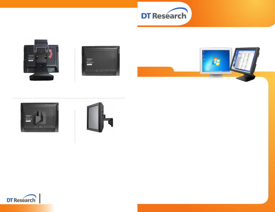
Mounting
The DT Research Integrated LCD System is designed to be secured to VESA-compliant mounting
arms or stands. This is accomplished by equiping the standard metal base on the rear of the display
unit. The VESA-compliant mounting holes at the rear of the device will mate with VESA mounts or
arms to meet the requirements of the deployment.
Remove the detachable base by pressing
1.
upward to remove the cover, then unscrewing
the four screws attaching the base to the
display.
Attach the new VESA-compliant mounting
3.
device or stand to the display.
The display without the base.
2.
The display successfully mounted on a
4.
VESA-compliant mounting arm.