Component removal, Crankshaft pulley installation – Vortech 1990-1995 5.7L TBI Truck/SUV User Manual
Page 9
P/N: 4GB020-010
©2002 Vortech Engineering, LLC
All Rights Reserved, Intl. Copr. Secured
22FEB02 V1.1
(LT. TRUCK (4GB V1.1))
1.
COMPONENT REMOVAL
A. Disconnect the battery (negative lead).
B. Remove and set aside the following components:
• Top portion of the fan shroud
• Accessory drive belt
• Cooling fan assembly
• Crankshaft pulley
• Air filter canister assembly and hose
• Intake air resonator (detach from inner fender)
• Alternator from bracket (place on manifold)
• Power steering pump pulley (use puller)
• Power steering pump pulley (DO NOT disconnect lines)
• Power steering bracket
2.
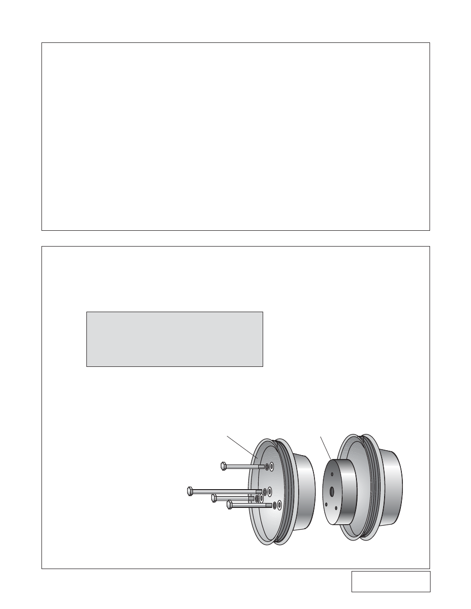
CRANKSHAFT PULLEY INSTALLATION
A. Remove the crankshaft pulley from the engine if
not already done.
B. Place the Vortech provided crank pulley and
spacer inside the stock pulley.
C. Line up bolt holes and, if necessary, press pieces
together or pull them together by gradually tight-
ening the bolts.
D. Reinstall the pulleys as a unit onto the crankshaft
balancer assembly using three 3/8-16 x 2-3/4"
bolts and one 7/16-20 x 4-1/4" center bolt pro-
vided.
Fig. 2-a
1
NOTE: Depending on the model year of the ve-
hicle, the stock pulley location (against
the balancer) may need to be switched
with the Vortech pulley (check that the
pilot of the spacer has a snug fit into the
I.D. of the accessory drive pulley).
3 BOLTS: 3/8-24 x 2-3/4"
SPACER
NEW ADDITIONAL PULLEY
CENTER BOLT: 7/16-20 x 4-1/4"