Vortech 1999-2006 4.8L/5.3L/6.0L Light Truck/SUV User Manual
Page 26
P/N: 4GL020-010
©2008 Vortech Engineering, LLC
All Rights Reserved, Intl. Copr. Secured
08OCT08 v5.0(99-07 GM Trk (4GLv5.0))
16
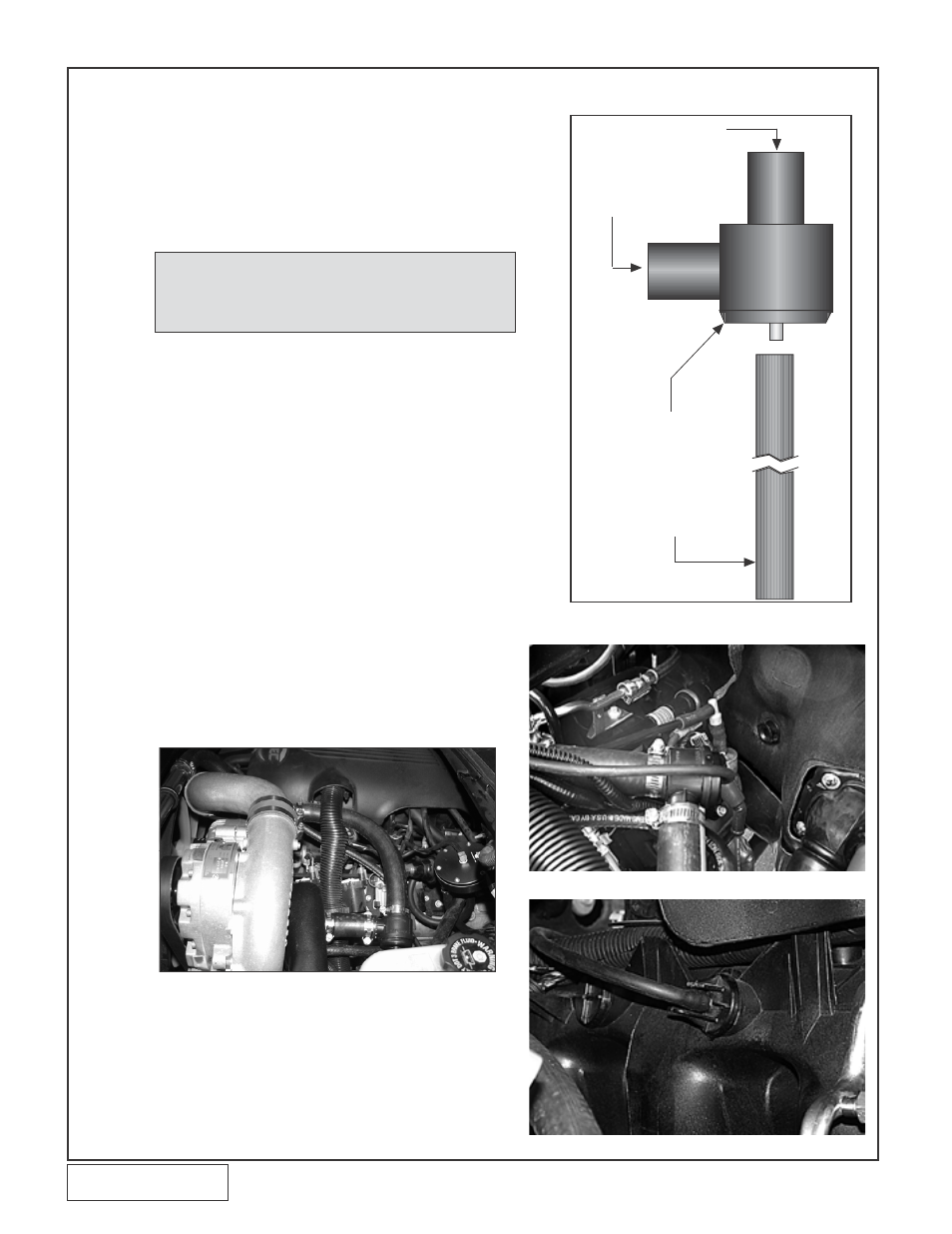
Fig. 13-a
13. SUPERCHARGER BYPASS VALVE InSTALLATIOn
A. Connect a 3” length of 1” hose from the barb on
the supercharger inlet duct to the outlet of the
bypass valve.
B. Using the supplied #16 hose clamps, connect the
barb on the aluminum discharge duct to the inlet
of the bypass valve using the supplied 1” hose.
(See Fig. 13-a.)
NOTE: Some vehicles may require trimming of the
engine cover to clear various components.
If necessary, trim the cover to clear the
bypass valve hose.
Fig. 13-b
Fig. 13-d
C. Install and tighten hose clamps on each connec-
tion.
D. Using the supplied 5/32” vacuum line and TEE
fitting, connect the bypass valve pressure port to
the manifold vacuum hose that is connected to
the fuel pressure regulator. (See Fig. 8-c.)
E. 2004-2005 Models: Locate the hard plastic line
running to the driver’s side rear of the engine.
Remove the hard line from the rubber hose.
F. 2004-2005 Models: Install the supplied 90° PCV
into the rubber hose on the engine.
G. 2004-2005 Models: Cut the hard plastic line to
reach the PCV valve and connect them with the
supplied length of 3/8” hose. (See Fig. 13-c.)
H. 2004-2005 Models: Locate the capped-off
manifold vacuum port on the passenger’s side
of the intake manifold. Using a file or hacksaw,
remove the tip of the capped-off section. Us-
ing the supplied 5/32” vacuum line connect the
bypass valve pressure port. (See Fig. 13-d.)
Fig. 13-c
5/32" HOSE
ø
SUPERCHARGER
DISCHARGE TUBE
BYPASS VALVE
AIR INLET
DUCT