TrakPower VR-1 Dual Racing Charger User Manual
Page 14
14
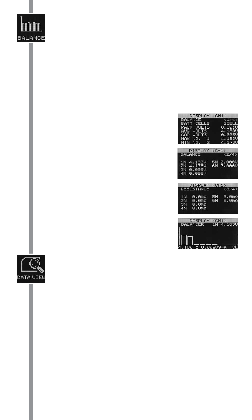
7. BALANCE
Displays lithium battery information such as number of cells connected, overall pack voltage,
average cell voltage, individual cell voltages, gap voltage, minimum and maximum cell number
and voltage and internal resistance for each cell. Cell voltages are also displayed in a bar graph.
The charger will detect the number of cells connected to the charger via the balance adapter.
To enter the balance function, locate the Balance icon as shown above left, connect battery
and press the dial. A balance start delay screen and confi rmation screen will appear prior to
balancing. You will need to verify that the correct number of cells is connected to the balance port
of the charger prior to balancing.
While or after balancing has been completed, you can rotate the jog dial to view the various data
that is displayed as listed below.
Use the jog dial to scroll through the screens to view other information such as all individual cell
voltages and the internal resistance of the cells. The last data screen displays the cell voltages
in a graph form.
A. Displays information such as cell number, pack voltage, average
cell voltage, gap voltage, highest and lowest cell voltage.
B. Displays individual cell voltages
C. Displays resistance of individual cells.
D. Displays cell voltages in bar graph form.
8. DATA VIEW MENU
This menu option shows various types of data pertaining to the input or output of the charger.
This menu consists of four different screens and can be seen only before a function has started,
or after a function has ended (not while a function is being performed).
DATA VIEW 1/4:
A. INPUT VOLTAGE: Shows the DC voltage at input lead.
B. OUTPUT VOLTAGE: Shows the DC voltage at banana jacks. It is important to understand that the
condition of the connector lead on the battery and the charger’s output can affect the accuracy
of the voltage reading.
C. BATTERY TEMPERATURE: Shows the temperature of the battery as measured with the optional
temperature sensor. If no sensor is connected the display will show “0.0°F”.
D. HIGH TEMPERATURE: In conjunction with the Battery Temperature feature above, VR-1 will constantly
record the highest measured temperature of the battery which is connected to the output.
E. BATTERY RESISTANCE: Will measure the battery’s internal resistance starting 2 minutes AFTER
discharge has stopped, and is shown in milli-ohms (
). Battery resistance will not be measured
if cell voltage is lower than 1.0V for NiCD/NiMH batteries for 3.0V for Li-Ion/LiPo batteries. This
is because the most important time to judge a battery’s internal resistance is when it is closer
to full charge. A lower resistance value is better, indicating the charger can likely condition the
battery more effi ciently and accurately. IMPORTANT: This value can be greatly affected by the
quality of the connection between the battery and VR-1’s output. A solid physical connection
is important to having a good electrical connection. High quality components in the battery’s
own lead and the adapter lead between the battery and charger is also very important. Silicon