Important precautions, Installation, Solder connections – TrakPower MS-1 Brushless ESC User Manual
Page 4: Throttle calibration, Programming
Important Precautions
•
Disconnect the battery from the ESC immediately if the ESC or battery becomes hot!! Allow
the ESC or battery to cool down before reconnecting.
•
NEVER use more than the specifi ed voltage on the ESC’s input.
•
ALWAYS mount the ESC in a position where free air can fl ow across it during operation.
•
ALWAYS monitor ESC temperatures.
•
Always turn on the transmitter before connecting the battery to the ESC.
•
Always disconnect the battery from the ESC when not in use.
•
Make sure the input battery is fully charged before connecting to the ESC, so the low voltage
cutoff feature can function properly.
•
Do not attempt to use with brushed motors.
•
Use heat shrink tubing to insulate any bare wires between the motor battery and ESC, and
from the ESC to the motor, to prevent a short circuit.
•
Allow the ESC to cool before touching.
•
Do not run the car near water! Never allow water, moisture or any foreign material onto the
ESC’s PC board.
•
Do not allow metal/conductive materials to accidentally make contact across all motor/
battery posts.
•
Never turn on the ESC before plugging it into the receiver and switching on the transmitter.
•
Keep out of reach of children.
•
TrakPower is not responsible for incidental damage or personal injury as a result of misuse
of this product.
Installation
Refer to your vehicle’s manual for the best mounting location and position on your chassis.
Always mount in a location where it will receive maximum airfl ow over and around the unit.
The MS-1 ESC features a CNC machined aluminum case that functions as a heat sink and helps
reduce operating temperatures. Once the mounting location has been determined, use the
included mounting tape to secure the ESC to the chassis.
Included are fi ve 200mm pieces of 12AWG silicon wire for the motor and battery connections.
You will need to supply the battery connector of your choice. It is highly recommended to make
one solder connection at a time so that there is no possibility of making an incorrect connection
which could result in permanent damage to the ESC and/or motor.
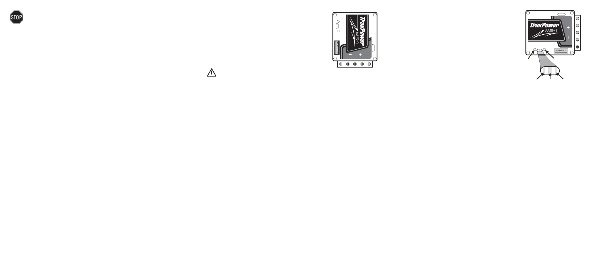
Solder Connections
1. Begin with solder post “A”. Heat up the solder post by
positioning the iron tip in the cutout section of the post. Apply
a small amount of solder to the post. Next, heat up the tinned
wire to get the solder fl owing. Apply a small amount of solder
to the iron tip, then set the wire into the solder post cutout
and heat both the wire and post together. Once the solder
begins to fl ow at the joint, apply solder in small amounts until
the wire and post have a solid connection.
IMPORTANT: Only apply the solder in small amounts.
Applying solder in large amounts will cause excessive
solder drip and potentially make connection to the next post.
Once the wire has been connected to the solder post, solder the other end of the wire to the “A”
tab on the motor. Repeat for “B” and “C” connections.
2. Solder the included red wire to the “+” (positive) solder post in the same manner as the motor
wires. The other end of this wire will be soldered to the battery connector of your choice. If
using a dual pin type connector, such as Deans
®
or Traxxas
™
, be sure that the “+” is connected
to the “+” on the connector.
3. Solder the remaining black wire to the “–” (negative) solder post as listed above. The other
end of this wire will be soldered to the negative pin on the selected connector type. Again,
note proper polarity and ensure the black wire from the negative (–) solder post on the ESC is
connected to the negative (–) pin on the connector.
4. Install the included sensor wire by plugging into the ESC fi rst and then the motor. TrakPower
MS Series brushless motors include a clip screw for the sensor wire. See the TrakPower
Brushless Motor manual for installation of the clip screw.
5. Connect the ESC lead into Channel 2 of the receiver and secure the power switch to the
desired location on the chassis by using a small piece of double sided mounting tape.
Throttle Calibration
Before the ESC can be used, throttle calibration must be performed to ensure the throttle is
setup properly. Be sure that all trims and sub-trims are set to ZERO before performing calibration
and that throttle and brake end points are set to maximum. Use a small diameter screwdriver
or similar to adjust the ESC. Failure to do so may result in the inability to complete calibration
or possibly case forward or reverse input when the trigger is at neutral.
Note: If using a Futaba transmitter, the throttle channel will need to be reversed prior to calibration.
1. Turn on transmitter.
2. With the small screwdiver, press and hold the Modify button (“M”) on the ESC. This button is
located on the left side of the LEDs as shown above in the diagram.
3. Turn ESC on.
4. ALL LEDs will illuminate once power is applied.
Release the Modify button (“M”) at this time. After
releasing the Modify button, the green LED will fl ash.
5. Move the trigger to the full throttle position. The
green LED will turn solid. Hold the trigger in position
until the red LED begins to fl ash.
6. Move the trigger to the full brake position. The red
LED will turn solid. Continue to hold the trigger in the
brake position until the blue LED begins to fl ash.
7. Return the trigger to the neutral position. The blue
LED will turn solid. All LEDs will fl ash simultaneously 3
times to complete throttle calibration.
Programming
1. Turn on transmitter.
2. Plug in battery and turn the ESC on. The blue LED will illuminate. Note: If 0° of advanced
timing is currently selected, the blue LED will fl ash indicating the ESC is in “blinky” mode.
Otherwise the LED will be solid.
3. Press and hold the Setting (S) button on the ESC and release once all LEDs have illuminated.
The green LED will remain lit after releasing. This signals that the fi rst programmable feature
(Voltage Cutoff) is ready to be adjusted. Pressing the S button will advance through the features.
Each LED or LED combination will correspond to a particular feature. Use the below chart as a
reference.
4. To modify or change the setting within a feature, press the Modify (M) button. The M button
will need to be pressed a certain amount of times to match the desired setting. Example:
Pressing the M button twice while the Red LED is illuminated will change the drive mode to
“Forward/Reverse”. Use the below chart as a reference.
To determine which setting a particular feature is currently on, use the S button to locate the
correct feature. Press and hold the M button. The LEDs will then turn off and begin fl ashing. The
current setting is displayed by the number of times the LEDs are OFF (not on).
5. After choosing a particular setting for a feature, the LEDs will then repeat the selection by
fl ashing the corresponding amount of times. This is displayed by the number of times the LEDs
are OFF (not on).
When programming is completed, press and hold the S button until all LEDs illuminate and then
release. Once the ESC returns to the blue LED, the ESC is ready for use.
See the quick reference chart on other side for programming:
Modify
Green
Blue
Red
Setting
M
S
ABC
LEDs
MS
A
B
C
A
B
(–)
(+) C