Part 1 - uprights, Step 1 – TracRac IM TracONE User Manual
Page 7
TracRac Inc. 994 Jefferson St. Fall River, MA 02721 l 800-501-1578
Instruction Manual
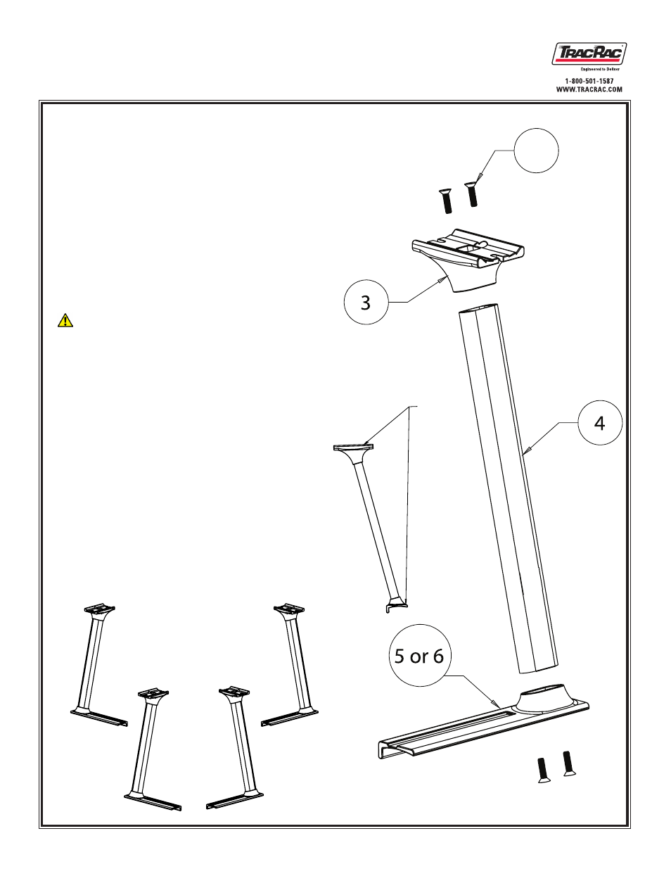
1.1 Upright Assembly
First take the upright (Item 4) and insert it into a
1.
modular saddle (Item 3).
Bolt the saddle through the top by using two 3/8”-16
2.
flat head cap screws (Item 12) and tighten using
an 7/32” Allen Wrench (or 7/32” Allen Drive Bit).
Torque the 3/8” -16 FHCS to 32 ft-lbs. We recom-
mend threading both flat head cap screw initially by
hand to ensure that you don’t cross thread the bolt.
1.1.1 When tightening the 3/8” flat head cap screws
ensure that the allen key is fully seated in the bolt so
that it will not strip
Now take the upright and saddle and bolt it to the
3.
modular base (Item 5)
Bolt the base through the bottom by using two
4.
3/8”-16 flat head cap screws (Item 12) and tighten
usingan 7/32” Allen Wrench (or 7/32” Allen Drive
Bit.) Torque the 3/8” -16 FHCS to 32 ft-lbs.
For the other front upright repeat steps one through
5.
four, except use (Item 6) in step three.
Repeat Steps 1-5 on each of the uprights
6.
1.1.2 NOTE: Item 5 and Item 6 are mirror images of each
other. Reference the packing checklist to confirm what
part to use.
Step 1
Part 1 - Uprights
12
Figure 1.1
Note:
Both
surfaces
must be
parallel
with each
other