Internal wiring diagram (qe2) – TFC Group Towerchron QE2 User Manual
Page 44
36
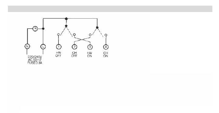
INTERNAL WIRING DIAGRAM (QE2)
NB • Carry out wiring installation using appropriate diagram as shown.
NB • Plug in unit and secure to the base by tightening fixing screw.
Important note:
For fully pumped systems the switch located at the rear of the “QE2” must be moved to the right - into the “fully
pumped” position
This manual is related to the following products:
See also other documents in the category TFC Group Relay:
- Grasslin SB-Digi+ 24/7 Digital Socket Box Timeswitch (16 pages)
- IHT-GPT01 (24hr) & IHT-GPW01 (7day) (2 pages)
- EMD120 (18 pages)
- Immersion Heater Timer Code: IHT-Digi 20 (20 pages)
- STA600BP(Topica 600) (2 pages)
- V86/1,2,3,4 Digi 322 (8 pages)
- Famoso 601 (24 Hr) (2 pages)
- Feeling RF Room Thermostat (42 pages)
- Famoso 1000 (Hard Wired) (3 pages)
- Famoso 1000 RF (2 pages)
- Famoso 505 (24 Hr) (9 pages)
- Tactic 371.1 Plus Digital Timeswitch (15 pages)
- Tactic 571.1 Plus Digital Timeswitch (10 pages)
- Tactic 571.1 (2 pages)
- Talento 371 Mini Plus (11 pages)
- Talento 892 Plus (43 pages)
- Talento 371 Plus (9 pages)
- Talento 471 Plus (18 pages)
- Talento 791 Plus (10 pages)
- Talento 891 (34 pages)
- Tunus 502 (2 Channel) (5 pages)
- Tunus 771 (11 pages)
- Trealux 510 Staircase Switch (24 pages)
- Trealux 710 (7 pages)
- Trealux 310 (4 pages)
- RFWRT (4 pages)
- HWPRS (4 pages)
- ECO ET1 (2 pages)
- ECO ET2 (2 pages)
- ECO ET3 (2 pages)
- ECO ET4 (3 pages)
- Towerstat REM STT/REM (22 pages)
- Towerstat SP STTR/SP (21 pages)
- STTR/F (19 pages)
- Grasslin QEG-1 (2 pages)
- Grasslin QEG-2 (2 pages)
- Towerchron QM1 (20 pages)
- Towerchron QM2 (20 pages)