TFC Group STTR/F User Manual
Page 10
Mounting the Receiver onto the optional wall
box:
1. Remove the front cover of the Receiver
2. Mark the holes position for the wall box
3. Drill two holes and insert the wall plugs until
they are flush with the wall surface
4. Pull the wires into the wall box and fasten the
wall box onto the wall
5. Connect the wires (see wiring diagram)
6. Securely fasten the Receiver to the wall box
with the two machine screws provided
7. Replace the front cover and installation is
complete.
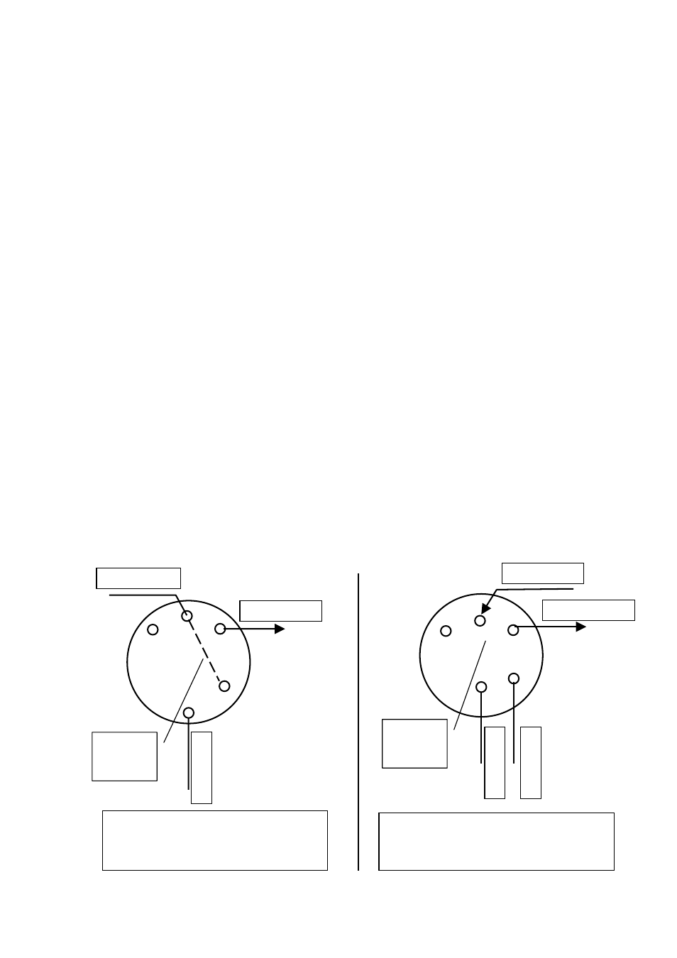
Wiring for 230v or volt-free applications
The Receiver has a volt-free contact, but comes
from the factory with a pre-wired red link wire which
puts volts onto the switch. Leave the link in place
for mains switching, or remove the link for volt-free
switching.
Connections for mains switched load:
Leave the link wire in place, and connect the
switched-live input of the load to the normally
open contact (marked SL (on))
input of the
load to the normally open contact (marked
Connections for volt-free switching:
Remove the link wire. Connect the looped
terminals of the boiler between common (marked L
in) and normally open contact (marked SL (on))
Live
supply
Neutral supply
Live output
230V
Leave red
link wire
in place
Live from load
Switched live output
Live supply
Neutral supply
Remove
red link
wire