Wiring diagram, Set-up – TFC Group Tunus 772 User Manual
Page 5
28
29
GB
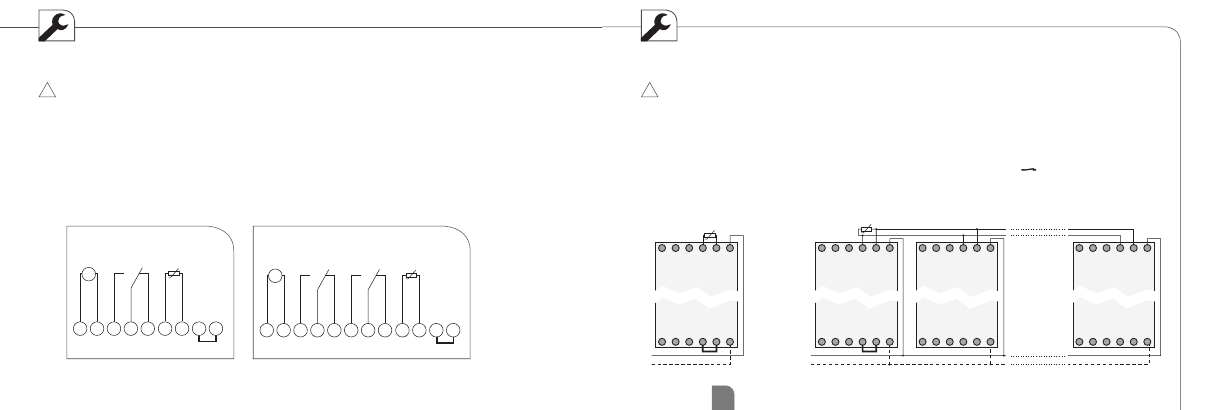
1 channel
CH1
M
~
Sensor
}
B1 B2
L N 1 2 3 + –
2 channel
Sensor
}
B1 B2
L N
M
~
CH1
CH2
1 2 3 5 6 7 + –
5 6 7
1 2 3
N
B1 B2
L
+ _
L
N
5 6 7
1 2 3
N
B1 B2
L
+ _
L
N
5 6 7
1 2 3
N
B1 B2
L
+ _
5 6 7
1 2 3
N
B1 B2
L
+ _
max. 10
Wiring diagram
If you connect the sensor to the + and
- terminals, you must connect a jumper
between terminals B1 and B2
If you operate several devices on one
sensor, this jumper may only be used for
one device
!
Set-up
The device - twilight switch and timer - only acti-
vates the output (terminals 1 and 5) when all three
conditions are fulfilled:
• brightness is lower than the adjusted value
• the adjusted delay time has passed
• the timer is set to = ON
If you connect the sensor to the + and
- terminals, you must connect a jumper
between terminals B1 and B2
If you operate several devices on one
sensor, this jumper may only be used for
one device
!