Defender series surge + pdu user manual – SurgeX Defender Series Surge + PDU User Manual
Page 3
Defender Series Surge + PDU User Manual
© SurgeX
REV-C
Page 3
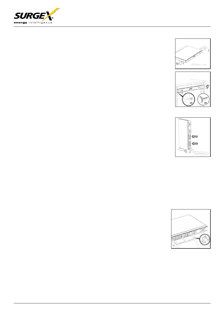
o To Install Tower Configuration – Option A
•
Use a Phillips screwdriver and (6) 6/32 x ½” flathead screws to attach the
base stand (figure 2-a)
•
Place the Defender Series unit on a flat, stable surface in an upright position
resting on the base stand (figure 2-b)
o To Install Rack Mount Configuration – Option B
•
Use a Phillips screwdriver and (5) 6/32 x ¼” flathead screws to attach the
left rack bracket (figure 3-a)
•
Use a Phillips screwdriver and (6) 6/32 x ¼” flathead screws to attach the
right rack bracket (figure 3-a)
•
Insert the Defender Series unit into an available 1RU rack space from the
front of the rack (figure 3-b)
Product is designed for U-Space mounting only
•
Use (4) thumbscrews to secure the left and right rack brackets to the rack
rails (figure 3-b)
•
Use (4) cage nuts to secure the 4 thumbscrews to the rack (figure 3-b)
•
Connect the Power Cables
o Connect the ancillary server equipment power plugs to the IEC output power
receptacles located on the rear panel of the Defender Series unit. Distribute
the equipment load evenly between the receptacle banks (figure 4-a)
o To properly protect your system, connect all ancillary server equipment
(including UPS/Battery Backup) to the SurgeX Defender Series output power
receptacles; Refer to Common Configurations
section for reference
o Check
that the equipment you have connected to the Defender Series meets
the following electrical rating requirements:
•
SX-DS-L630-FP:
IMPORTANT: ONLY CONNECT EQUIPMENT RATED FOR USE WITH
NORTH AMERICAN 120/230VAC SPLIT PHASE
•
SX-DS-L530-FP:
IMPORTANT: ONLY CONNECT EQUIPMENT RATED FOR USE WITH
NORTH AMERICAN 120VAC SINGLE PHASE
•
SX-DS-520-FP:
IMPORTANT: ONLY CONNECT EQUIPMENT RATED FOR USE WITH
NORTH AMERICAN 120VAC SINGLE PHASE
•
SX-DS-IEC-FP:
IMPORTANT: ONLY CONNECT EQUIPMENT RATED FOR USE WITH
230VAC SINGLE PHASE
•
Secure the Power Cables – (optional)
o Secure equipment power cords to the cable organizer (if desired) using
cable ties or zip ties, to prevent accidental removal (figure 5-a)
5-a
4-a
3-b
3-a