StorCase Technology DX100-SNC User Manual
Page 2
Kingston Technology Company D89-0000-0069 - Rev. A00
2
Single-Connect Adapter Board
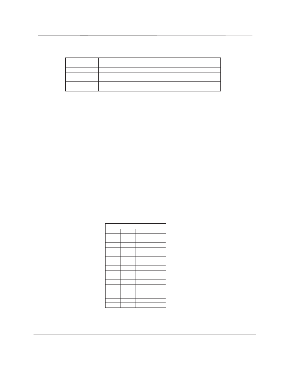
X = Jumper Installed
Table 2: SCSI ID Selection
SCSI ID = 0
X
SCSI ID = 1
X
SCSI ID = 2
X
X
SCSI ID = 3
X
SCSI ID = 4
X
X
SCSI ID = 5
X
X
SCSI ID = 6
X
X
X
SCSI ID = 7
X
SCSI ID = 8
X
X
SCSI ID = 9
X
X
SCSI ID = 10
X
X
X
SCSI ID = 11
X
X
SCSI ID = 12
X
X
X
SCSI ID = 13
X
X
X
SCSI ID = 14
X
X
X
X
SCSI ID = 15
SCSI Jumper Positions
ID3
ID2
ID1
ID0
Table 1: Motor Start Controls
DLY REM Motor Spin Function
OPEN OPEN Motor spins up at DC power on.
OPEN GND Motor spins up only when SCSI "start" command is received.
GND OPEN Motor spins up after delay of (12* seconds) x (the numeric
value of SCSI target ID of the drive) from DC power on.
GND GND Reserved. Drives not implementing this option will spin up
when SCSI "start" command received.
*This value may be reduced by the drive manufacturer to reflect the worst case time duration of peak current drains at
the 12-volt or 5-volt source (or both) during spin up. The delay should never exceed 12 seconds.
Activity LED Out Signal
The Activity LED Out Signal, provided by the drive, is intended to support a drive activity LED. This signal is de-
signed to pull down the cathode of the activity LED indicator during periods while the drive is forming SCSI opera-
tions.
Spindle SYNC
The Spindle SYNC signal is provided for spindle synchronization between multiple drives. Synchronized drives
should be of the same or equivalent model types. (Synchronization protocol and the electronic requirements for the
SYNC signal are defined within the drive specifications. Spindle synchronization is managed by the SCSI command
set.)
The Single-Connect Adapter Board provides 2 sets of Spindle SYNC pins. To implement this option, a jumper wire
must be run from the SYNC pin on the Adapter Board to a SYNC pin on another drive or Adapter Board. This signal
may be jumpered in a daisy chain configuration for up to 7 drives (8-bit), or 15 drives (16-bit).
SCSI ID Select
Each device on the SCSI bus must have a unique SCSI ID number. The SCSI ID Select pins allow the selection of
an appropriate SCSI ID (0-7 for 8-bit connections; 0-15 for 16-bit connections). On the 8-bit version of the Adapter
Board (DX100-SNC), the last set of option pins (ID3) are not used.