Installing the receiving frame – StorCase Technology S20A133 User Manual
Page 16
S20A133 User's Guide - Rev. A02
StorCase Technology, Inc.
Installation
9
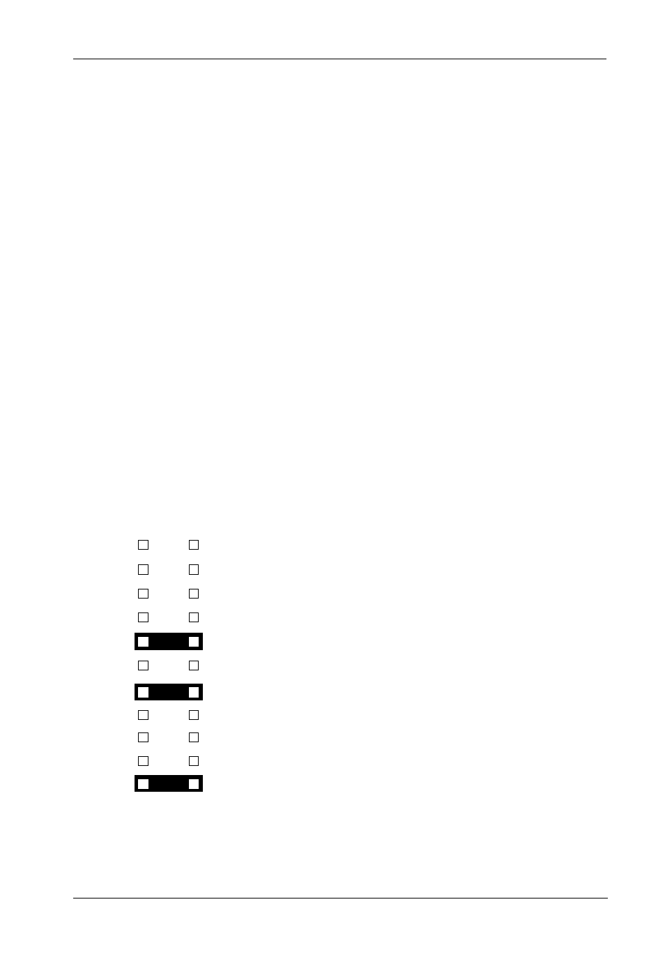
Figure 7: Receiving Frame Motherboard J3 Option Pin Connector
Installing the Receiving Frame
NOTES: For SCSI Ultra160 operation, the DE300 requires Ultra160 chassis and cabling.
These newly-designed Ultra160 68-pin DE300 (with blower) carriers are inter-
changeable with other Ultra160 68-pin DE300 (with blower) receiving frames and
older Ultra160 68-pin DE300 receiving frames (without blowers).
Older Ultra160 68-pin DE300 carriers are NOT designed for use with the newer
Ultra160 68-pin DE300 (with blower) receiving frames (overheating may occur if
there is inefficient air flow within the enclosure).
The drive should be installed into the carrier before installing the receiving frame into the
mounting bay of a computer or expansion chassis.
NOTE:
Use a #2 Phillips screwdriver during this procedure.
1.
Turn OFF power to the computer.
2.
Open the computer system according to the manufacturers instructions. If neces-
sary, temporarily remove any expansion boards that may make installation difficult.
3.
To select the DE300 unit ID remotely through the computer system or external ex-
pansion chassis, the appropriate cable from the system must be connected to the
option pins (1-8 on connectors J3A1, J3B1, J3C1) on the rear of the receiving frame
as shown in Figure 7.
0542B
Pin 1
Pin 2
ID0
Pin 3
Pin 5
Pin 7
Pin 9
Pin 11
Pin 13
Pin 15
Pin 17
Pin 19
Pin 21
Pin 4
ID1
Pin 6
ID2
Pin 8
ID3
Pin 10 Buzzer Enable
(Factory-Installed Jumper is located on J3A1 connector only!)
Pin 12 RLED
Pin 14 Fan Failure Indication
Pin 16 Sync
Pin 18 RMTST
Pin 20 DLYST
Pin 22 For Factory Use Only
(Factory-Installed Jumper - Do Not Remove!)