StorCase Technology Ultra320 DE100 User Manual
Page 19
StorCase Technology, Inc.
Ultra320 DE100 User's Guide - Rev. A00
12
Installation
Mounting
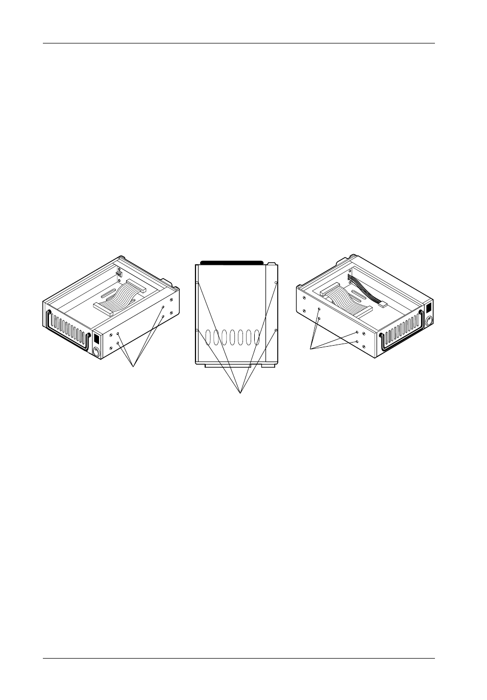
Holes (Right)
Mounting
Holes (Bottom)
Front of Unit
Mounting
Holes (Left)
0086
IMPORTANT NOTE: In order to use remote ID selection from a computer or expansion
chassis, the Unit ID number on the Ultra320 DE100 receiving
frame must be set to "0" with the provided alignment tool. Refer
to the section "Selecting the Unit ID Number" later in this manual
for the Unit ID selection procedure.
4.
With the drive carrier locked in place inside the receiving frame, install the
Ultra320 DE100 into the 5.25 drive opening in the computer or expansion
chassis. Use the appropriate guides to position the Ultra320 DE100, and fasten
it into place with the four (4) #6-32 Phillips Flat Hd. screws provided. Figure 9
illustrates the location of the mounting holes. Mounting holes are provided on
each side and the bottom of the receiving frame to accommodate a variety of
mounting configurations. Use the mounting holes which best suit the computer
or expansion chassis configuration.
Figure 9: Receiving Frame Mounting Holes
5.
Adjust the front of the receiving frame so the carrier slides freely in and out on
the receiving frame guides. The position of adjoining peripheral units may require
adjustment.
6.
To connect the drive to a Remote Activity LED in the computer system or
expansion chassis, connect the appropriate cable(s) to W1 Pins 9 & 10 on the
receiving frame motherboard as shown in Figure 5.
7.
Connect the I/O cable from the host adapter to the receiving frame. The Pin 1
indicator on the cable must be properly aligned. Refer to Figure 5 for the correct
Pin 1 location.
NOTE:
No onboard termination is provided on the Ultra320 DE100.
External termination must be provided.