Spectrum Controls 1771sc-IMI16 User Manual
Page 5
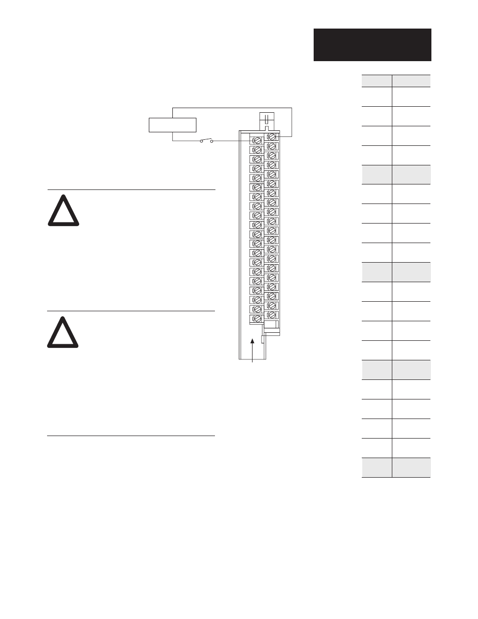
Figure 2
Connection Diagram
Installation Data
AC/DC (220/240 V) Input Module
Cat. No. 1771sc-IMI16
5
2
4
6
8
10
12
14
16
18
20
22
24
26
28
30
32
34
36
38
40
220/240 V
AC/DC Supply
L1
L2
L1
220/240 VAC High
or DC Positive
L2
AC Low
or DC Common
(Actual wiring runs in this direction.)
Always follow the applicable codes and
laws in your area.
WARNING
EXPLOSION HAZARD
Never connect or disconnect equipment
while circuit is live unless area is known to
be non-hazardous.
Failure to observe these precautions can cause
equipment damager, personal injury or death.
WARNING
HIGH LEAKAGE CURRENT
Before wiring field devices to your module,
ensure that the PLC has been properly
grounded
Failure to observe this precaution can cause
equipment damage or personal injury.
!
!
Terminal
Function *
1
Input 00 +
2
Input 00 -
3
Input 01 +
4
Input 01 -
5
Input 02 +
6
Input 02 -
7
Input 03 +
8
Input 03 -
9
Not used
10
Not used
11
Input 04 +
12
Input 04 -
13
Input 05 +
14
Input 05 -
15
Input 06 +
16
Input 06 -
17
Input 07 +
18
Input 07 -
19
Not used
20
Not used
21
Input 10 +
22
Input 10 -
23
Input 11 +
24
Input 11 -
25
Input 12 +
26
Input 12 -
27
Input 13 +
28
Input 13 -
29
Not used
30
Not used
31
Input 14 +
32
Input 14 -
33
Input 15 +
34
Input 15 -
35
Input 16 +
36
Input 16 -
37
Input 17 +
38
Input 17 -
39
Not used
40
Not used
* Input numbers are
shown in octal.