Ch 3 – Speck Electronics X.Sum User Manual
Page 21
Chapter 3
Operation Section
17
This modular plug connects the BB-03 Breakout Box to the multifunction I/O
connector [13] on the rear panel of the X.Sum.
These balanced ¼" TRS jacks are the left and right outputs of the Mix-B bus.
The signal present at these jacks is adjusted by the Monitor [7] control on the
front panel.
Another function of the breakout box connector will also let you connect your
own external preamps to the X.Sum should you want to experiment with a
more "colored" sound. The Mix-A (pre-fader) output jacks on the breakout
box bypass the output circuits and the master level control of the Xsum so you
can connect a pair of external preamps should you want to experiment with
"character" sounds.
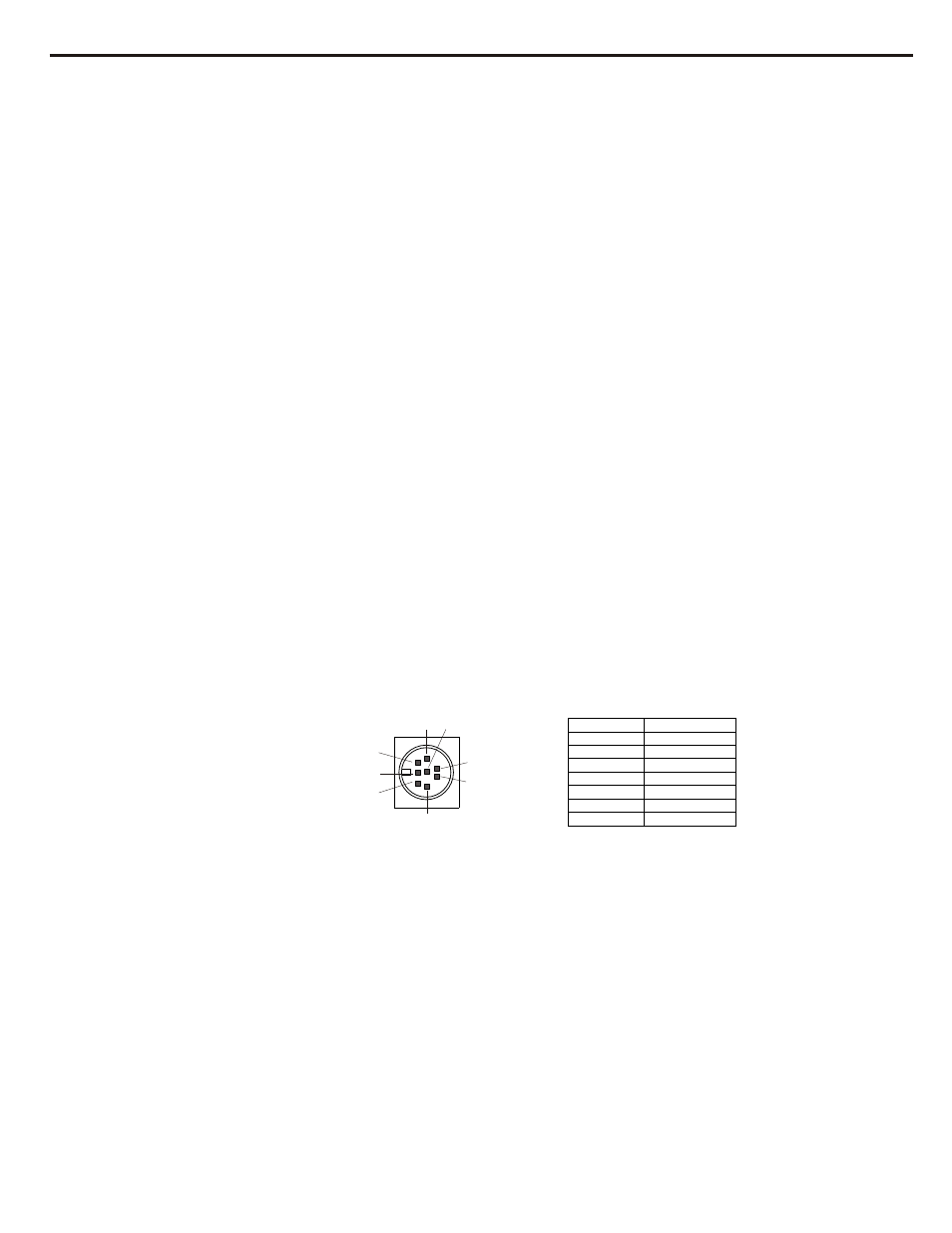
The DC power cable that comes from the power supply connects to this 8 pin
circular connector. This connector and its respective plug is keyed so they will
only fit in one direction. For power supply installation instructions, refer to
the Interface & Setup Section in this manual.
The following connector illustration and chart as shown in figure 6 represents
the DC voltages to the 8 pin circular connector required to power the X.Sum.
4
7
2
8
1
6
3
5
PIN 1
0 VDC
PIN 2
0 VDC
PIN 3
+16.5 VDC
PIN 4
0 VDC
PIN 5
-16.5 VDC
PIN 6
PIN 7
0 VDC
PIN 8
Figure 6
16. Mix-A (pre fader)
Ouput Jacks
17. D.C. Power Inlet
15. Mix-B Output Jacks
-16.5 VDC
+16.5 VDC
14. Breakout Box
Connector