Included in the box, Return side installation: steps 1-7, Supply side installation – Sanuvox SR+ User Manual
Page 2: Figure a. sr+ support frame
NOTE: If installing over a heating source : The SR+ uses a built-in thermistor to sense airflow. The thermistor is set at 80°celcius (176°
Fahrenheit) when airflow passes over the thermistor, the thermistor cools slightly to switch the SR+ on. This is an effective method in controlling
the SR+ especially with new high efficiency variable-speed fans. Because the thermistor is sensitive to temperature change, if installing the SR+
on the supply side, install the SR+ far enough away from the heating source that the air will be less than 80°celcius (176° Fahrenheit).
Follow Steps 1-2 for Return side Installation
Sanuvox SR+
UV ‘J’ Lamp
Frame
INCLUDED IN THE BOX:
- Gloves
- Installation Instructions
- 6 x Self-Tappping Hexagon 1/4 Sheet Metal Screws (#8)
- 4 x Stainless Steel Phillips Screw 8-32 1/2"
8.5”
5.5”
3
4
5
7
6
Turbulator
Reflecting Tube
3
Return side Clamp Post (Default)
Return side Clamp Post (Default)
Supply side Clamp Post
Supply side Clamp Post
Installation Kit
RETURN SIDE INSTALLATION: STEPS 1-7
Carefully remove UV
Lamp from packaging.
Use incl. cotton gloves to
guarantee a clean Lamp
after handling.
To install UV Lamp,
remove Reflecting Tube
by removing the four (4)
screws on both sides of
the Reflecting Tube.
Insert UV Lamp with the 4
pin end into the clamp
assembly. Do not over
tighten wing nut. Plug the
Lamp into the white plug.
Re-install the Reflecting
Tube. Make sure the
Turbulator will be facing
into the airflow.
To mount the frame, take
the frame support and
draw an outline on the
inside of the frame onto the
duct. Allow for a 1/8" space
around the marking. Cut
the hole which should
measure 5.5" x 8.5".
Mount the Support Frame
to the duct using the six (6)
Sheet Metal Screws. Once
t h e f r a m e h a s b e e n
mounted, insert the SR+
guided by the four (4)
mounting posts.
See Figure A.
Secure the SR+ to the
frame with the four (4)
Stainless Steel Phillips
Screws
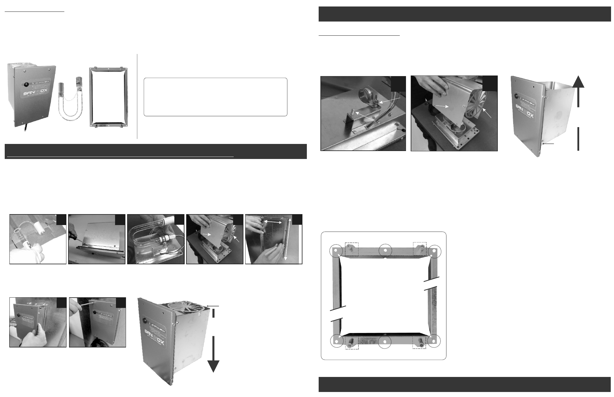
Six (6) holes to be used to mount the
Frame to the duct wall with included
sheet metal screws
Four (4) Mounting Posts (two top & two
bottom of Frame) holds the SR+ in
place with four stainless steel screws
A
A
A
B
B
B
B
B
A
B
Figure A.
SR+ Support Frame
SAFETY CONSIDERATIONS
Only trained and qualified service personnel should install, repair, or service HVAC equipment. Untrained personnel can perform basic maintenance
functions such as changing Lamps. Trained service personnel should perform all other operations. When working on HVAC equipment, observe
precautions in the literature, tags and labels attached to the unit or accessory, and other safety precautions that may apply. Follow all safety codes.
1
2
NOTE: If the SR+ is to be installed on the SUPPLY side please refer to “Supply Side Installation”on opposite page
4
Turbulator
Reflecting Tube
Location: The preferred location for installation of the Sanuvox SR+ UV System is in the return duct as the air will be treated before the filter and coil.
Make sure site can be supplied with the necessary power requirements. The SR+ should preferably be plugged into a conditioned dedicated 110V
outlet. If one is not available, an extension cord may be used. If the SR+ is to be installed on 220V, undo the four side screws to gain access to the
ballast and switch the ballast from 110V to 220V (there is a small switch on the ballast itself) & cut the plug to hard wire to 220V supply. Direct UV
exposure is dangerous to plastics. Wrap exposed plastic and wiring to shield from direct UV exposure (The Sanuvox wire-set is Teflon coated which
makes them resistant to UV exposure). The purifier can be mounted in a horizontal or vertical position (in the same direction of airflow). More than one
unit can be used in homes equipped with more than one air handler.
Return Installation
Airflow moves downward
through Turbulator
Supply Installation
Airflow moves upward
through Turbulator
For supply side or up-flow systems, the
SR+ ships as a default RETURN
installation unit. If the SR+ is to be installed
in another orientation (i.e. supply side, up-
flow, etc.) the UV Lamp clamp must be
installed on the opposite threaded post with
the Reflecting Tube re-installed with the
Turbulator facing into the airflow.
Reinstall Reflecting Tube with Turbulator
facing into the airflow.
Follow the remaining steps 5-7 on the
RETURN SIDE INSTALLATION.
B
Turbulator
Turbulator
SUPPLY SIDE INSTALLATION
1-888-726-8869 www.sanuvox.com
A