RTA Products RTA-Q203 User Manual
Page 4
7
8
8
10
14A
14B
Aprete el boton para separar las partes
11
12
X3
RTA-2203
P.8
RTA-2203
P.7
C
4PCS
6X40 mm
F
6PCS
4X14 mm
9
11
E
3PCS
6X25 mm
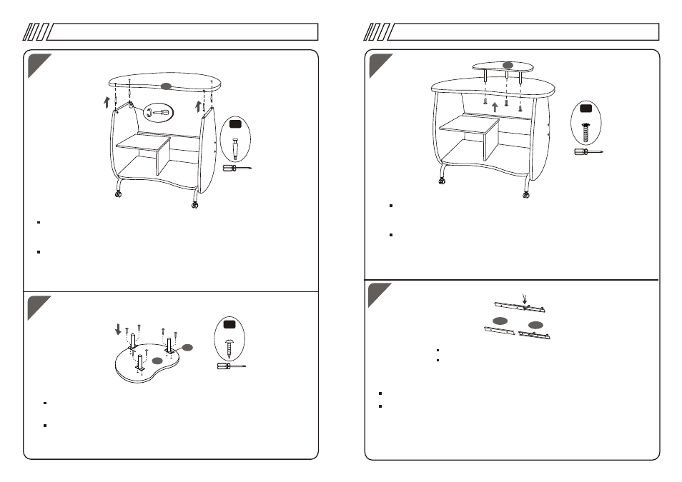
Insert the Clam Bolts (C) at the back side of the Main Panel (8). Then
assemble the Main Panel (8) to the lateral left and right panels ( 1 & 2),
and tight the bolts at the inside face of the lateral panels.
Coloque los pernos de Ajuste C en la cara posterior del Panel Principal (8)
y hagalos coincidir con los huecos de los Cuerpos Laterales (1 y 2).
Luego ajuste las tuercas de la cara interna de los paneles laterales con el
destornillador girando en el sentido de las ajugas de reloj.
Using screws (F) fix the Tubes for Monitor panel ( 12) to the Monitor
Panel ( 11)
Use Tornillos F para fijar los Tubos de Panel de Monitor (12) al Panel
de Monitor (11)
With screws (E) assemble this unit to the Main Panel (8). Note that
Screws (E) have been inserted to part 12 and have to be taken out
when fixed to the Main Panel (8).
Use Tornillos E para ensamblar esta Unidad al Panel Principal (8).
Favor notar que los tornillos E han sido insertados en la Parte 12 y
deberan extraerlos para fijarlos al Panel Principal (8)
Pull down the Black Platic Button to separate both parts of Sliders (14)
Apriete la pieza de plastico negro para separar las dos partes de los
deslizadores (14)
Pull down the black plastic to make A and B separate.