Datel 20A User Manual
Page 10
USQ Series
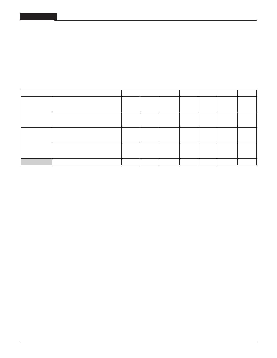
Load Conditions ➀
Performance Specifications
1.2V
OUT
1.5V
OUT
1.8V
OUT
2.5V
OUT
3.3V
OUT
5V
OUT
12 to 24V
OUT
Load Step = 50 to 75% of I
OUT
Max.:
Peak Deviation, typ.
115mV
110mV
125mV
100mV
170mV
125mV
100mV
Settling Time to ±1% of Final Value, max. ➁
200µs
200µs
225µs
200µs
100µs
100µs
100µs
C
OUT
= 10µF || 1µF
Load Step = 75 to 50% of I
OUT
Max.:
10µF || 1µF
Peak Deviation, typ.
115mV
110mV
125mV
100mV
100mV
125mV
100mV
Settling Time to ±1% of Final Value, max. ➁
140µs
200µs
225µs
200µs
100µs
100µs
100µs
Load Step = 50 to 75% of I
OUT
Max.:
Peak Deviation, typ.
120mV
TBD
105mV
90mV
105mV
TBD
85mV
Settling Time to ±1% of Final Value, typ. ➁
115µs
TBD
170µs
65µs
65µs
TBD
40µs
C
OUT
= 220µF || 1µF
Load Step = 75 to 50% of I
OUT
Max.:
Peak Deviation, typ.
120mV
TBD
90mV
90mV
105mV
TBD
50mV
Settling Time to ±1% of Final Value, typ. ➁
150µs
TBD
150µs
70µs
65µs
TBD
25µs
Switching Frequency (min./typ./max. kHz)
120/150/180 120/150/180 170/185/200 230/255/280 132/147/162 220/240/260 190/210/230
Dynamic Load Response and Switching Frequency
DATEL has performed extensive evaluations, under assorted capacitive-load
conditions, of the dynamic-load capabilities (i.e., the transient or step
response) of USQ Series DC/DC Converters. In particular, we have evalu-
ated devices using the output capacitive-load conditions we use for our
routine production testing (10µF tantalums in parallel with 1µF ceramics), as
well as the load conditions many of our competitors use (220µF tantalums
in parallel with 1µF ceramics) when specifying the dynamic performance of
their devices.
➀
The listed pair of parallel output capacitors consists of a tantalum in parallel with a multi-layer ceramic.
➁
∆I
O
/
∆t = 1A/1µs, V
IN
= 48V, T
C
= 25°C.
To avoid the added cost of constantly changing test fixtures, we have veri-
fied, during our device characterization/verification testing, that 100% testing
under the former conditions (the 100µF || 1µF load), which we guarantee,
correlates extremely well with the latter conditions, for which we and most of
our competitors simply list typicals.
If you have any questions about our test methods or would like us to perform
additional testing under your specific load conditions, please contact our
Applications Engineering Group.
10
2 0 A , S I N G L E O U T P U T D C / D C C O N V E R T E R S