Bfs/tc series thermal stages – Physitemp Instruments BFS-TC User Manual
Page 7
BFS/TC SERIES THERMAL STAGES
1.0 GENERAL
DESCRIPTION
1.1
Physitemp manufactures three freezing stages for use with microtomes. All stages operate in the
same way and reach the same minimum temperature. They differ only in surface area, as follows:
BFS-3TC has stage area 3cm x 4cm
BFS-5TC has stage area 3.8cm x 4cm
BFS-30TC has stage area 7.5cm x 8cm
This manual also covers the FRM/TC series freezing microtomes which comprise a BFS/TC Stage and
and ERMA Microtome.
1.2
The BFS/TC THERMAL STAGE
The stage is a metal plate, 1/16” thick. Heat is
supplied to or withrawn from the specimen by
means of an electric heat pump attached to the
underside of the plate, and excess heat is con-
ducted away by cooling water. When the stage is
operated below room temperature, a curtain of
cold air flows over the specimen, minimizing
condensation and improving temperature con-
formity.
1.3
The CONTROLLER will maintain stage temperature at any point between -40° and +60°C.
Resolution is 1/10°C. The controller can also be used as a digital temperature readout. See Section 1.4.
1.4
The DIGITAL THERMOMETER AND TEMPERATURE PROBE. A thermocouple microprobe
is included with the equipment. If this probe is connected to the external probe input, the controller can
be used as an independent thermometer. Range is -100° to +200°C and resolution is 1/10°C.
1.5
Optional PUMP AND TANK UNIT, PTU-3. The stage needs running water for operation. If
access to a water tap is inconveneint, a circulating pump with a small water tank is required.
2.0
SETTING UP THE THERMAL STAGE
Sections 2.1 to 2.5 describe setup of the BFS/TC with tap water. If a Pump and Tank Unit is to be used
to circulate cooling water, see Appendix 1.
2.1
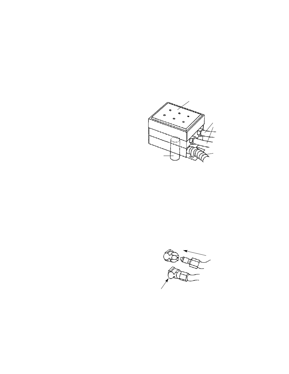
ATTACH WATER TUBES
The two 5’ water tubes connect the controller
to the water supply. Connections are self-seal-
ing when disconnected to prevent water spills.
To connect, push in firmly. Squeeze the metal
tab to disconnect.
Connect one of the tubes to the inlet (IN) on
the rear of the controller. This tube should be
connected to laboratory water supply.
Connect the second tube to the outlet (OUT) on the rear of the controller. Allow the other end to run to
waste.
Do not turn water on until the stage has been connected.
2
PUSH TO CONNECT
SQUEEZE TAB IN TO RELEASE
MOUNTING
HARDWARE
TEMPERATURE
CONTROLLED SURFACE
WATER
TUBES
ELECTRICAL
CONNECTIONS