Valve controllers – Parr Instrument Valve Controller User Manual
Page 6
Valve Controllers
P a r r I n s t r u m e n t C o m p a n y
6
Rear Panel
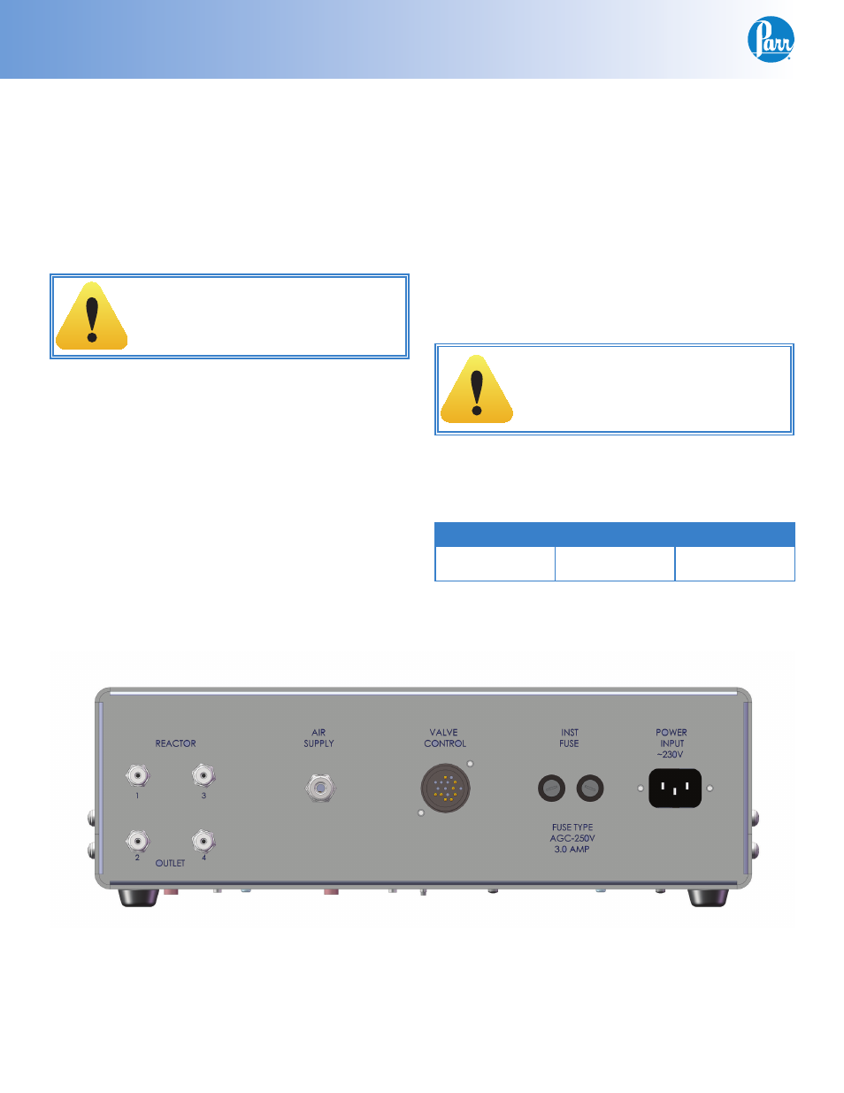
Back View 4877 Valve Controller
(Model with 4 air outlets, 230 Volt shown)
Air Supply
Connect a dry air supply to the 1/4” Male Tube con-
nector provided on the rear panel of the 4877 Valve
Controller. The operating pressure of the air supply
is determined by the air actuated valves supplied
with your reactor system. The controller and the
supplied tubing are limited to a maximum working
pressure of 105psig.
Warning:
The controller and supplied tubing are
rated to a maximum working pressure of
105psig.
Reactor Outlet
There are up to 12 air outlets provided on the rear
panel of the 4877 Valve Controller. Each outlet is
numbered 1-12. Use the tubing supplied to con-
nect the corresponding air actuated valve to the
appropriate outlet connection. This is unique with
each system but can be determined by the IO map
provided on the Process Controller CD supplied with
your particular reactor system.
Valve Control
The VALVE CONTROL connection on the rear panel
of the 4877 Valve Controller is to be connected to the
Process Controller provided with your system using
the supplied control cable.
Protective Fuses
Main fuses are mounted on the back panel of the
valve controller. These fast acting, 250VAC, 3 amp
fuses are intended to protect the controller and sup-
ply in case of a fault condition.
Warning:
Unplug unit before servicing. For contin-
ued protection against possible hazard,
replace fuses with same type and rating of
fuse.
Fuses
The following are 4877 Controller fuses which are
intended to be fi eld serviceable.
Fuse
Rating
Part number
Main Fuse(s)
Fast acting, 3
Amp, 250VAC
139E24