Nstallation, General instructions — 8 4875 connections — 8, 4875 c – Parr Instrument 4875 User Manual
Page 7: R2 r4, 4875 power controller rear panel
4875 Power Controller
P a r r I n s t r u m e n t C o m p a n y
8
I
nstallatIon
g
eneral
I
nstructIons
Set the controller near the reactor on a sturdy bench or
table where there is convenient access to an electrical
outlet capable of carrying up to 15 amperes. Leave a
space of at least twelve inches between the controller
and the heater of the reactor so that the controller will
not be affected by radiant heat.
Refer to applicable Process Controller Operating
Manual for specific installation instructions.
4875 c
onnectIons
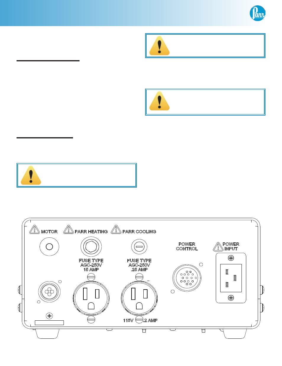
Labeled connections are provided on the rear panel of
the controller.
Parr Cooling Only:
The Parr Cooling output connector is to be used only
with Parr Instrument Company cooling solenoid valve
assemblies supplied with the appropriate cooling power
cord.
Parr Heating Only:
The Parr Heating output connector is to be used only
with Parr Instrument Company heater assemblies
supplied with the appropriate heater power cord.
Motor:
Secure the clamp on motor cord to the
controller with the provided screw next to
the motor socket for safety purposes.
The Motor output connector is to be used only with
Parr Instrument Company motor assemblies supplied
with the appropriate motor power cord.
The Power Control connection is for connection to the
Process Controller.
The Power Input connection is for connection to a
suitable power source. Only use Parr cord sets supplied
with the controller. Take care to position the controller
so that the power cord can easily be accessed if power
needs to be removed from the system.
1:1
4875 115 VOLT INPUT W/90 VDC MOTORS
MAW
SIZE
E
A2800HC2EB
12-17-03
VGM
COMPANY.
OR BETTER
64
MACHINED SURFACES:
UNMARKED RADII .03"
ANGULAR ... ±1/2°
.000 .... ±.003
.00 .... ±.010
1/X .... ±1/64
UNLESS OTHERWISE SPECIFIED
IN INCHES
TOLERANCES
DRAWN IN 3rd ANGLE PROJECTION
DO NOT SCALE DRAWING
BY
12-16-03
R5 WAS IDM, 215F SERIES DECAL,[EC10295] 06-24-09 JPR
R2 ADDED (2)SA1140RD06,SA1132RP04, REV 2961HC, WAS SA1632RD08 [EC4217]; 04-19-07 MAW
FOR
REVISIONS
DESCRIPTION
DRAWN
DATE
DWG NO.
SCALE
PARR INSTRUMENT CO.
211 53rd STREET
MOLINE, ILLINOIS 61265
SHEET 1 OF 4
R1 REVISED & REDRAWN 01-18-02 [EC3562]
DATE
4875 POWER CONTROL LAYOUT
R3 ADDED 331E, 1111E MTG [EC4363]; 10-22-07 MAW
APPROVED
BY
PROPRIETARY
NEITHER THE DRAWING
NOR INFORMATION
CONTAINED HEREIN
MY BE COPIED,
REPRODUCED, OR
OTHERWISE USED
WITHOUT WRITTEN
PERMISSION FROM
PARR INSTRUMENT
R4 DEL 91F, LISTED MTG HARDWARE [EC4573]; 04-10-08 MAW
R3
R1
R4
LIGHT
LIGHT
5
A1220EEB, SPEED CONTROL
KNOB
LIGHT
(2) SA1140RD06, 4-40 X 3/8 RHMS
8-32 KEPS NUT
542E
LOAD
1375E, TERMINAL BLOCK
(2) TN1332HL, 6-32 KEPS NUT
SPEED CONTROL
828E2EE
85E2EE
831DD, CONNECTOR
POTENTIOMETER (REF)
1119E, RELAY
828EEE
828E2EE
1532E, FILTER 6 AMP
LINE
1451HC, PAD
SWITCH
(2) SA1632RD06, 8-32 X 1/2 RHMS
(2) TN1632HL, 8-32 KEPS NUT
1587E
A1710E, TRIP RELAY
(2) TN1632HL, 8-32 KEPS NUT
(2) SA1140FT06, 4-40 X 3/8 FHMS
1111E, MODULE
W/4-40 MTG SCREW
SWITCH
BREAKER
828E2
(2) TN1332HL, 6-32 KEPS NUT
1466E, RECEPTACLE
1531E, FILTER 3AMP (SHOWN)
OR
GROUND STUD (REF)
(2) TN1632HL
190F, GROUND SYMBOL (REF)
3022HC, ISOLATOR MTG BRACKET
1588E, ISOLATOR
(2) TN1632HL, 8-32 KEPS NUT
(4) SA1332RD08, 6-32 X 1/2 RHMS
(4) TN1332HL, 6-32 KEPS NUT
R2
R4
(4) 1664HC, RUBBER FOOT
95F, DATA LABEL
(4) SA1632RD06, 4-40 X 3/8 RHMS
(8) TA1332PP06X
6-32 X 3/8 PH PAN HD
LT GRAY
10.50 REF
5.00
REF
139E10, FUSE, .25 AMP
90VDC 1/8HP
801E_SERIES
215F SERIES
R2
6-32 X 3/8 RHMS
(4) SA1332RD06
2961HC
BOTTOM PANEL
2964HC
FRONT PANEL
9.40 REF
4875 Power Controller Rear Panel