Final steps, Meter pin outs – Parr Instrument PDM User Manual
Page 6
- 6 -
PDM Installation
Final Steps
Close the controller and replace the two screws on the back panel. Plug the 4838 controller back in,
and turn it on. The PDM display should read zero when the motor is not turning.
It is useful to check that the settings on the display are set correctly. Check these against the defaults
listed in the back of these instructions.
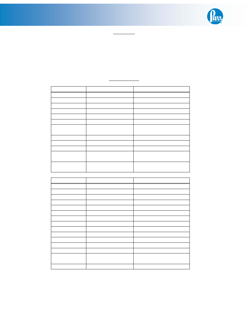
Meter Pin Outs
2082E
Color:
Attaches to:
Pin 1
Black
Terminal Block 4
Pin 2
White
Terminal Block 3
Pin 3
Pin 4
White
A2104E Harness Pin 1
Pin 5
Pin 6
Black
A2104E Harness Pin 2
Pin 7
Orange
2083E Primary Temp
Controller Terminal 14
Pin 8
Blue
Terminal Block 3
Pin 9
Pin 10
Pin 11
White
2083E Primary Temp
Controller Terminal 10
Pin 12
Black
2083E Primary Temp
Controller Terminal 9
2083E
Color:
Attaches to:
Pin 1
Violet
1119E SSR Terminal 4
Pin 2
Red
1119E SSR Terminal 3
Pin 3
T/C Cable RTD only
T/C Jack (-) RTD
Pin 4
T/C Cable
T/C Jack (+)
Pin 5
T/C Cable
T/C Jack (-)
Pin 6
Pin 7
Pin 8
Pin 9
Black
Comm Receptacle Pin 5
Pin 10
White
Comm Receptacle Pin 3
Pin 11
Black
Terminal Block 4
Pin 12
White
Terminal Block 2
Pin 13
Pin 14
Orange
542E High Limit Switch
Position 2
Pin 15
Blue
Terminal Block 3