Parr Instrument Series 5000 User Manual
Page 8
- 8 -
5000 Series Multiple Reactor System
INSTALLATION (continued)
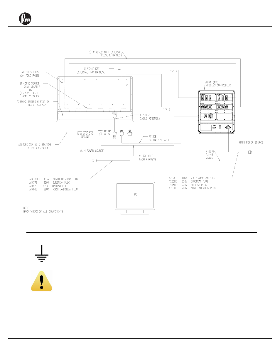
Diagram 1: Layout Diagram of Multiple Reactor System
Connect the external grounding
strap between the heater and
stirrer assembly.
The A1330E2 Heater Cable
assembly is to be fixed with
screws to prevent access to
live electrical components.
There will be a metal bracket on each
end of the cable with a screw on it.
Unthread the screw and line it up with
the port on the chassis. Then tighten
the screw to fix the cable in place.
Turn on the power switches located on
the front of the controller and the stirrer
assembly. If present, make sure the
stirrer local/remote switch is in the
remote position. If there is no stirrer
local/remote switch present on this unit,
no adjustment is necessary.
- 1341 (16 pages)
- 1108 (20 pages)
- 1901 (2 pages)
- 1104 (12 pages)
- 1121 (4 pages)
- 1755 (2 pages)
- 1552 (1 page)
- DP8340R Series (52 pages)
- Attaching Platinum Fuse Wire (1 page)
- 1281 (2 pages)
- 1271 (2 pages)
- Performa Therm Liquid Calorimetric Thermometers (2 pages)
- 1108P (20 pages)
- 1356 (41 pages)
- 6300 (130 pages)
- 6200 (94 pages)
- 6200 (88 pages)
- 6100 (82 pages)
- 6510 (16 pages)
- 1564 (12 pages)
- 6400 (103 pages)
- 6400 (110 pages)
- 6772 (70 pages)
- 6725 (76 pages)
- 6755 (52 pages)
- 6750 (36 pages)
- 1108V (4 pages)
- 1108R (20 pages)
- Safety Rupture Disc Assemblies (8 pages)
- Magnetic Drive (16 pages)
- 44HC5 Metal Gaskets (1 page)
- Flexible Graphite Gaskets (1 page)
- Pressure Relief Valves (2 pages)
- Series 5100 (32 pages)
- Series 4520 (32 pages)
- Series 4530 (28 pages)
- Series 4540 (32 pages)
- Series 4550 (28 pages)
- Series 4560 (28 pages)
- Series 4570 (28 pages)
- Series 4580 (28 pages)
- Series 4590 (28 pages)
- Series 4555 (48 pages)
- 4575/76 HP/HT (24 pages)