Pressure relief valves – Parr Instrument Pressure Relief Valves User Manual
Page 2
Pressure Relief Valves
P
arr
I
nstrument
C
ompany
211 53rd Street • Moline, Illinois 61265 USA 1-309-762-7716 • 1-800-872-7720 • Fax: 1-309-762-9453
E-mail: [email protected] • http://www.parrinst.com
323M R04 12/10/14
Cooling Body
The A2599HC3 cooling body assembly is provided
when a Parr pressure apparatus is intended to be op-
erated above 350 °C. Cooling is necessary to limit the
temperature at the seals within the relief valve. To pre-
vent overheating, a steady flow of cold water should
be fed during all vessel operations at temperatures
above 350 °C. Tubing connections for flowing water
are provided on each sleeve, and a 10 foot length of
tubing is furnished to connect to a water source.
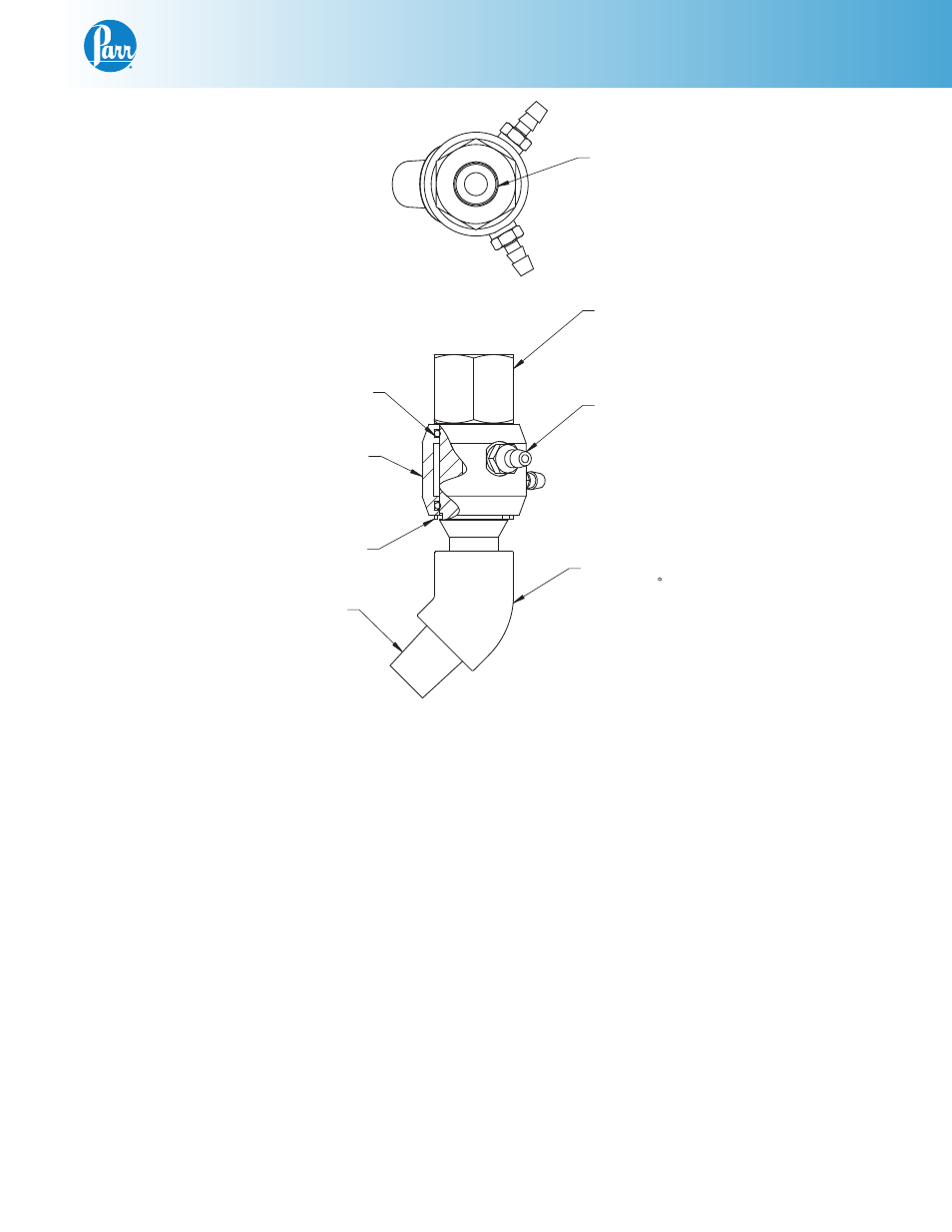
Servicing the Cooling Sleeve
The cooling sleeve has two O-rings which seal the
sleeve onto the cooling body. These O-rings will have
to be replaced after extended periods of service or
after excessive heating with no water flowing through
the sleeve. To replace the O-rings, remove the cooling
body from the elbow (see figure 3). After removing the
cooling body, rotate and pull off the cooling sleeve.
The O-rings can now be removed from the sleeve, be
careful not to scratch or damage the O-ring grooves.
Clean any accumulated lime deposits from the sleeve
and insert new O-rings into the grooves; then moisten
the O-rings and slide the cooling sleeve into place on
the cooling body.
Figure 3
A2599HC3
NOTE:
(1) FOR USE WITH JP0025TB06 TUBING
1/4 NPT REF
O-RINGS
2X 827HC
(SEE NOTE 1)
CLIP RING
825HC
COOLING SLEEVE
2683HC
1394HC3
154VB2
COOLING BODY
2X 2714HC
HOSE NIPPLES
ELBOW 45
1/4 NPT REF