Step 5 step 3 step 4 – ParkZone PKZ4300 User Manual
Page 3
• BA
TT
• THRO
• ELEV
• AILE (R)
• AILE (L)
• RUDD
• AUX1
Installing Landing Gear
1. Slide landing gear into allotted space on fuselage.
2. Fit should be snug, so it will not easily pull out.
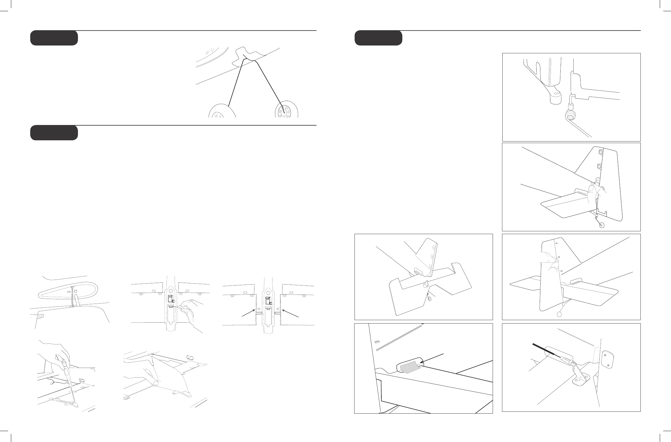
Attaching the Wing
1. Locate the wing set. Note the servos are located in
the bottom of the wing.
2. Select a wing half and slide in fuse, making sure
you slide the aileron servo lead in first (in allotted
hole in side of fuse). Pull aileron lead carefully
through fuse in order to allow wing tab and spar to
go into their allotted holes. Do the same with the
other wing half.
3. Carefully slide wing halves toward each other until
the wing tabs overlap.
4. Match up the holes on each tab and secure with
included screw.
5. Plug in the aileron connectors into the receiver.
The aileron leads will plug into the Y-harness
attached to the receiver. Confirm that the ailerons
are plugged into the proper leads and they are
operating correctly.
Attaching the Horizontal Stabilizer and
Rudder
1. Locate horizontal stab.
2. Carefully slide horizontal stab into fuselage, making
sure control surface horn is on top.
3. Use included strips (4 pieces) of clear tape to
secure stab to tail fillet. You should use 1 strip for
top and bottom of each side.
4. Locate rudder. Carefully snap tail wheel wire into
the clip on bottom of fuse as shown.
5. Carefully use hobby knife to slowly separate decal
from foam, only where three hinges are to attach
to stab. When decal is slightly separated from
the foam slide hinges between decals and foam
of stabilizer. Use the three pins that are supplied
to connect rudder to stab as shown. Do this by
pushing pins in carefully.
6. Install keepers on backside to secure pins
as shown.
7. Attach rudder and elevator pushrods to
respective control horns (outer holes of control
horns for both).
Note: It may be necessary to re-trim control
surfaces prior to flight.
(Optional) SFG Installation
1. Locate the SFG™ mounts from the accessory bag.
2. The lower SFG mounts feature screw alignment
pins to ease in the installation. Insert the lower SFG
mount into the positioning holes in the wing. Gently
install the upper SFG mount into the wing and
carefully press the mounts together.
3. Using a small Phillips screwdriver (#00 Phillips
screwdriver is recommended), secure the mounts
together using the included screws.
4. Slide the SFG surfaces into the mounts and secure
with clear tape. The SFGs are symmetrical and
when installed, the graphics will face the wing tip.
Always check ailerons prior to flight to make sure
they are not reversed!
Apply Tape
• BA
TT
• THRO
• ELEV
• AILE (R)
• AILE (L)
• RUDD
• AUX1
Wing Tab
Wing Tab
Step 2
Step 4
Step 5
Step 6
Step 7
Step 5
Step 3
Step 4
Step 3
Optional step for installing the Side Force Generators