NIBCO High-Performance Butterfly Valve User Manual
Page 9
A H E A D O F T H E F L O W
®
www.nibco.com
NIBCO INC. WORLD HEADQUARTERS • 1516 MIDDLEBURY ST. • ELKHART, IN 46516-4740 • USA • PH: 1.800.234.0227
TECH SERVICES PH: 1.888.446.4226 • FAX: 1.888.234.0557 • INTERNATIONAL OFFICE PH: +1.574.295.3327 • FAX: +1.574.295.3455
www.nibco.com
9
®
Revised 8/22/2013
Stem Packing Replacement Procedure
7.27 Remove valve from piping per procedure above.
7.28 Mark orientation of actuator in relation to valve body.
7.29 Remove actuator and all hardware from top of valve to expose gland flange (2).
7.30 Remove nuts (8) and lockwashers (7). Push upward on studs (9) and remove gland flange (2) from top of valve. Remove
stem retainer clips (3) and gland (4) from stem (1).
7.31 Being careful not to damage any seal surfaces, remove PTFE packings (5) from valve body (17) and discard.
7.32 Clean packing cavity and gland (4). Inspect for damage.
7.33 Install new packing assembly (5) into valve body (17). Slide gland (4) over stem with flat side towards packing. Install two
retainer clips (3) into stem above gland (4).
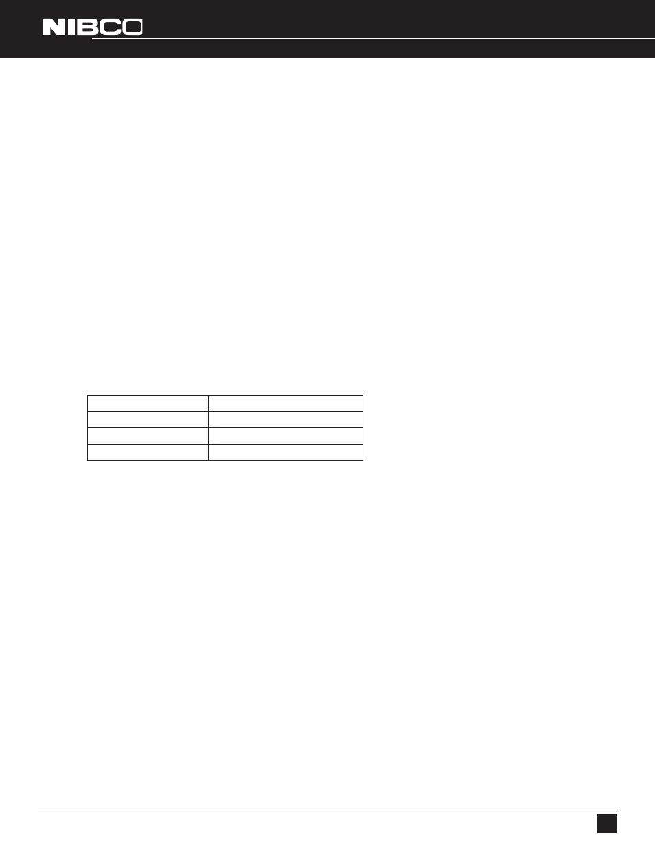
7.34 Slide gland flange (2) with studs (9) over stem and into cavity. Install lockwashers (7) and nuts (8). Tighten nuts evenly to
torque as follows:
VALVE SIZE
NUT TORQUE FT·LBS
2” - 6”
4 ft·lbs
8” - 14”
8 ft·lbs
16” - 30”
11 ft·lbs
7.35 Install actuator and hardware to top of valve in original orientation as marked. Tighten all fasteners securely.
7.36 Cycle actuator several times, then to CLOSED position. Visually inspect the disc to assure it is centered in the seat. If not,
refer to Section 4 for proper stop adjustment.
7.37 Open and close valve several times and check for proper operation before placing valve back in service.
Installation, Operation and Maintenance Instructions
NIBCO 6822 and 7822 Series High Performance Butterfly Valves