Drive alignment, Motor maintenance, Wheel and shaft maintenance – MK Plastics DHK-NW IO&M User Manual
Page 4: Arrangement 8 shaft flexible couplings, Drainage detail
M.K. Plastics Corp. Montréal, Québec www.mkplastics.com
Page. 4
Refer to the following procedure for belt tensioning -
1. Loosen motor plate adjustment bolts and move motor
plate in order that the belts can easily slip into the
grooves on the pulleys. Never pry, roll, or force the belts
over the rim of the pulley.
2. Adjust the motor plate until proper tension is reached.
For proper tension, a deflection of approximately 1/60”
per inch of center distance should be obtained by firmly
pressing the belt. Refer to Figure 8.
3. Lock the motor plate adjustment nuts in place.
4. Ensure pulleys are properly aligned.
When replacing belts, replace the entire set. After initial
replacement and tensioning, recheck belt tension after a few
days. New belts require a break-in period. Never use belt
dressing on any belts.
Drive Alignment
Pulley alignment is adjusted by loosening the motor pulley
setscrew and by moving the motor pulley on the motor shaft.
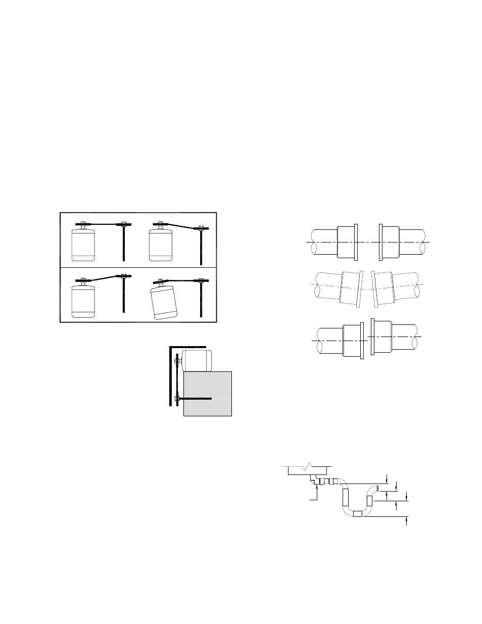
Fig. 9 illustrates correct and incorrect pulley alignment.
A recommended method of inspecting
the pulley alignment is shown in
Figure 10. With the shorter leg of a
carpenter’s square or other straight
edge lying along the case of the
motor, adjust the position of the motor
pulley (or the motor) until the longer
leg of the square is parallel to the belt.
Motor Maintenance
The three basic rules of motor maintenance are:
1. Keep the motor clean.
2. Keep the motor dry.
3. Keep the motor properly lubricated.
Blow dust off periodically (with low pressure air) to prevent
motor from overheating.
Some smaller motors are lubricated for life. Lubrication
requirements are normally attached to the motor. Use the
motor manufacturer’s recommendations for relubrication. If
this information is not available, the following schedule may
be used. Motors less than 10 HP running about eight hours a
day in a clean environment should be lubricated once every
five years; motors 15 to 40 HP, every three years. For motors
in dusty or dirty environments or running 24 hours a day:
divide the service interval by 4. Do not over lubricate.
Wheel and Shaft Maintenance
Periodically inspect the shaft and wheel for dirt buildup,
corrosion, and signs of excess stress or fatigue. Clean the
components. If the wheel is removed for any reason, make
sure that it is securely attached to the shaft before restarting
the fan.
Arrangement 8 Shaft Flexible Couplings
Coupling alignment should be checked after installation and
prior to start up. Alignment is set at the factory, but shipping,
handling, and installation can cause misalignment. Check
for misalignment between the coupling halves. Parallel
and angular misalignment and separation gap are shown
in Figure 11. Refer to coupling manufacturer’s installation
instructions for allowable misalignment and separation gap
tolerances. When correcting for misalignment using shims,
the shims should only be located under the motor. Do not
place shims under the shaft bearings. A dial indicator or
laser can be used for alignment where greater precision is
required. After aligning procedure, check for tightness of all
coupling component pieces and ensure that they are clean
from dirt and debris.
Drainage Detail
All DHK fans come as standard with outlet drains due to the
possibility of water or condensation that may occur. Proper
disposal of water must occur by connection of drain outlet to
a drainage system (by others). Piping must have adequate
pitch for proper runoff and be supported (if needed) to prevent
the possibility of sagging and overflow. The trap should be
filled before start-up.
A: Must be greater than system static pressure.
B: Must be greater than 1/2 of the system static pressure.
C: 1” water seal.
Correct
Incorrect
Incorrect
Incorrect
Figure 9 - Pulley Alignment
Correct
Incorrect
Incorrect
Incorrect
Figure 10
Separation
Angular
Misalignment
Parallel
Misalignment
Figure 11 - Flexible Couplings
A
B
C
Fan Drain
Dimension of A, B, C: Inches
Figure 12 - Drainage Detail