MK Plastics DHK-NW IO&M User Manual
Page 2
M.K. Plastics Corp. Montréal, Québec www.mkplastics.com
Page. 2
Pre-Installation
When the unit is removed from storage after a long duration,
all bearing grease should be purged and replenished with
fresh grease as per the lubrication decal. The motor should be
measured to verify that the resistance is still at a satisfactory
level compared to the value recorded prior to storage.
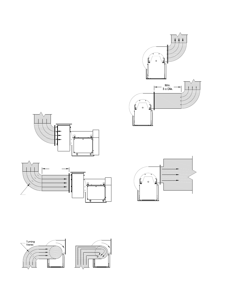
Inlet & Outlet Fan Installation
Efficient fan performance relies on the proper installation
of inlet and discharge ducts. Installations with poor inlet or
discharge configurations may result in reduced performance.
Restricted or unstable flow at the fan inlet can cause pre
rotation of incoming air or uneven loading of the fan wheel
resulting in increased system losses and sound levels.
Free discharge or turbulent flow in the discharge ductwork
will also result in system losses. Make sure the following
recommendations are followed.
Inlet Duct Turns
Installation of a duct turn or elbow too close to the fan inlet
reduces fan performance. To achieve full fan performance,
there should be at least three effective wheel diameters
between duct turns or elbows and the fan inlet.
Inlet Spin
A common cause of reduced fan performance is inlet spin. To
prevent this occurring, it is good practice to use turning vanes
in the duct to reduce the effects.
Discharge Duct Turns
Where possible, allow minimum three duct diameters between
turns or elbows and fan outlet. Fan performance is reduced
when turns are made immediately off the fan discharge.
Free Discharge
Avoid a free discharge into the plenum. This will result in
lost efficiency because it doesn’t allow for a static regain.
Fan Installation
Follow proper handling instructions given earlier.
•
Move the fan to the final mounting position.
•
Remove skid, crates, and packing materials carefully.
•
If supplied, place vibration pads or isolation base on
mounting bolts. Line up holes in fan base with bolts.
•
Place fan on mounting structure. Carefully level utilizing
shims as required at all mounting hole locations. Bolt
down the unit.
•
Any grout may now be used. Bolt the fan in position
before applying grout. Do not depend upon grout to
support rotating equipment.
•
Continue with Operations Checklist.
Additional instructions may be given for some fan sizes,
components and accessories in the submittal.
Turning Vanes
Min.
3 x Dia.
Figure 2 - Inlet Ducting
Good
Poor
Figure 3 - Inlet Spin
Good
Poor
Poor
Good
Figure 4 - Outlet Ducting
Figure 5 - Free Discharge