Wiring installation, Wiring diagrams – MK Plastics AXPR IO&M User Manual
Page 3
3
Wiring Installation
All wiring should be in accordance with local ordinances and the National Electrical Code, NFPA 70. Ensure the
power supply (voltage, frequency, and current carrying capacity of wires) are in accordance with the motor
nameplate.
Lock off all power sources before unit is wired to power source.
Due to the mounting location of AXPR fans, it is sometimes difficult to reach disconnect switches if mounted to the
unit. It is therefore recommended to remotely mount the switch for easier access.
Follow the wiring diagram in the disconnect switch and the wiring diagram provided with the motor.
Correctly label the circuit on the main power box and always identify a closed switch to promote safety (i.e.
red tape over a closed switch).
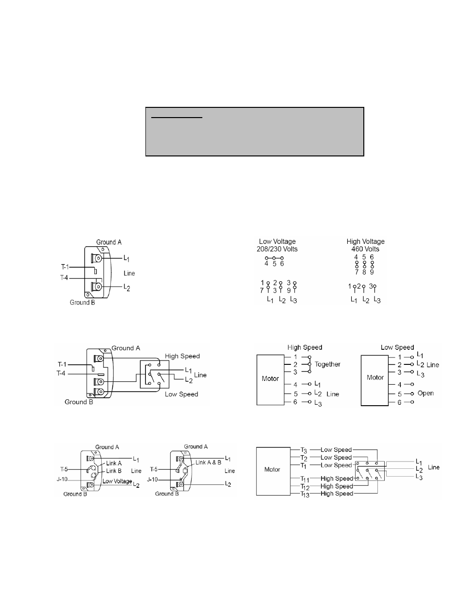
Wiring Diagrams
Single Speed, Single Phase Motor
When ground is required, attach to ground A or B with No. 6 thread
forming screw. To reverse, interchange T-1 and T-4 leads.
3 Phase, 9 Lead Motor
To reverse, interchange any 2 line leads.
2 Speed, 2 Winding, Single Phase Motor
When ground is required, attach to ground A or B with No. 6 thread
forming screw. To reverse, interchange T-1 and T-4 leads.
2 Speed, 1 Winding, 3 Phase Motor
To reverse, interchange any 2 line leads. Motors require magnetic
control.
Single Speed, Single Phase, Dual Voltage
When ground is required, attach to ground A or B with No. 6 thread
forming screw. To reverse, interchange T-5 and J-10 leads.
2 Speed, 2 Winding, 3 Phase
To reverse: High speed-interchange leads T11 & T12.
Low speed-interchange leads T1 & T2. Both speeds-interchange any
2 line leads.
Personal Safety
Disconnect switches are recommended. Place the disconnect
switch near the fan in order that the power can be swiftly cut
off in case of an emergency, and in order that maintenance
personnel are provided complete control of the power source.