LINK Systems Max Presence Sensing Device User Manual
Page 14
Link Lite Black Max Section 3 - Installation
3-9
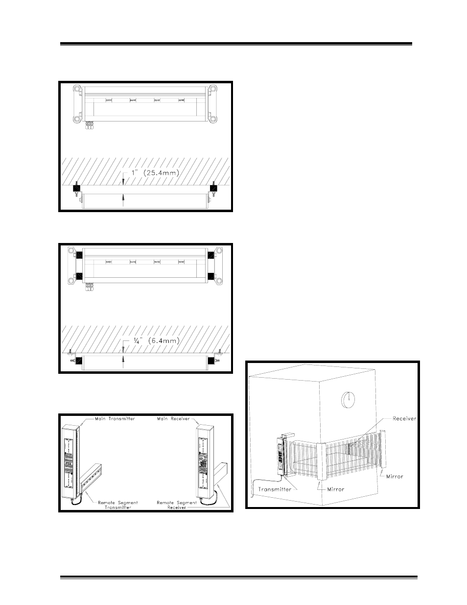
Also, the mounting arrangement is some-
what different for the remote segement units
as shown in Figures 3.9a and 3.9b.
Figure 3.9a:
Example of remote segment
Black Max unit mounting.
Figure 3.9b:
Alternate remote segment
Black Max unit mounting.
Figure 3.10:
Mount main and remote
transmitter and receiver units on the same
respective sides.
Black Max remote segment transmitter and
receiver units must always be mounted on
the same side of the machine, respectively,
as the main transmitter and receiver units as
shown in Figure 3.10
3.4.3 Use of Mirrors for Multi-Sided
Point of Operation or Perimeter
Safeguarding Applications
In some safeguarding applications mirrors
may be used to "bend" the sensing field
provided by main Black Max units to
provide two or more sided safeguarding for
point of operation or perimeter safeguard-
ing. Mirrors for this purpose can be
purchased from Link Systems. Since even
the finest quality mirrors do not reflect
100% of incident light and some diffusion
of light occurs, the maximum sensing field
distance between transmitter and receiver
will be reduced by about 10% per mirror
used. Figure 3.11 illustrates a three sided
point of operation safeguarding application.
NOTE!
Safety Distance, D
s
, must be
maintained on all sides of sensing field.
Figure 3.11:
Example of three sided point
of operation guarding on C frame press.