Lingenfelter L460030000 Lingenfelter RPM-001 RPM Activated Switch v4.01 User Manual
Page 3
Wiring (also labeled on module):
Wire Color
Label
Notes
White
Tach
This is the RPM input wire. This connects to your rpm signal wire.
Yellow
Normally
Off
This is the normally open (off) activation wire. This wire connects to ground when switch is
activated. This connects to the ground side of the device you plan to activate.
Gray
Normally
On
This is the normally closed (on) activation wire. This wire will open the ground path when
the switch is activated. This connects to the ground side of the device you plan to control.
Black
Ground
Connects to a vehicle ground.
Red
+ 12 V
Connects to a switched +12 volt source.
Red LED:
•
Comes on solid on start-up
•
When active RPM is reached, LED will blink at 18 Hz (fast)
•
Blinks at 2 Hz rate (slow) if RPM set below 500 rpm at
start-up with outputs disabled
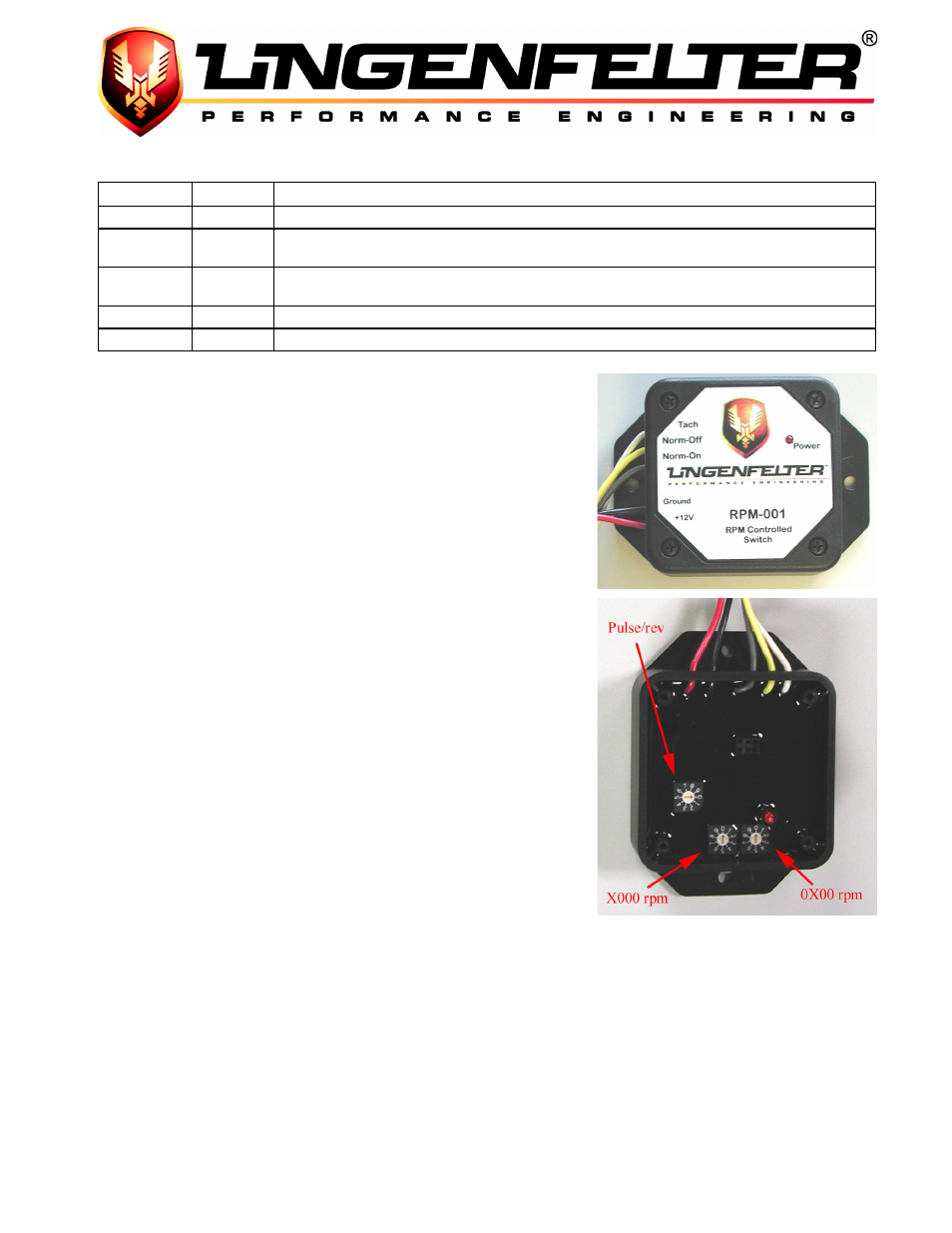
Settings:
•
Controlled by three (3) switches
o
Two (2) switches for selecting rpm (switches side by side)
o
Third switch for selecting pulse/rev. count
•
NOTE - see settings table on page 4
o
View module with wires exiting top, and 0 at 12 o’clock on
RPM selector switches
•
Changes to the rpm switch point settings must be done
with the ignition off
o
The switch positions are only read on start up
o
The RPM Controlled Switch will not work at RPM
levels below 500 rpm
Example settings:
GM LS1/LS6/LS2 V8 engines (connect to PCM TACH output)
•
1800 rpm switch point example
o
Upper switch set to 2 (for 2 pulses per revolution, LOW mode)
o
Left (X000) rpm switch on position 1
o
Right (0X00) rpm switch on position 8
Most GM V8 engine applications including L98, LT1 and LT4 engines (connect to PCM TACH output)
•
7200 rpm switch point example
o
Upper switch set to 4 (for 4 pulses per revolution, LOW mode)
o
Left (X000) rpm switch on position 7
o
Right (0X00) rpm switch on position 2
Page 2 of 4