Guardian 500 installation procedure – Labconco Protector Demonstration Hoods 3945021 User Manual
Page 29
Chapter 6: Maintaining Your Protector Demonstration Hood
Product Service 1-800-522-7658
25
Guardian 500 Installation Procedure
1. The enclosure comes prepared to except the Guardian™ 500 Airflow
Monitor.
2. First remove the large 1.19" dia. gray hole plug. See Figure 2. See
Figure 3 only to reference internal assembly of the airflow monitor.
Locate the elbow, locknut, and washer and install it in the 1.19" dia.
hole per Figure 6-2 and Figure 6-3. The enclosure baffle pivots down
to install the elbow, washer and locknut.
3. Cut the 1" hose supplied with the kit to 15.5" approximate length and
install it between the airflow sensor and the elbow.
4. Secure the Guardian 500 Airflow Monitor to the enclosure with double
stick tape as shown in Figure 6-4. The airway passage between the
alarm module and the enclosure is now complete.
5. Locate the metal hose cover and install with double stick tape per
Figure 6-4.
6. Locate the power supply transformer. One end should already be
connected to the two-pin connector labeled 15 VDC on the back of the
alarm module and through the strain relief bushing. If disconnected,
then reconnect to power the airflow monitor. Plug the 115V power
supply into a standard 115V duplex receptacle, the back of the
accessory FilterMate portable exhauster or the back of the accessory
light. For 230V, plug into a standard receptacle with your specific
outlet plug. (It is recommended that the airflow monitor be
connected directly to the FilterMate switched auxiliary outlet so
the airflow monitor is powered at the same time.)
7. Installation is now complete.
2
3
1
4
5
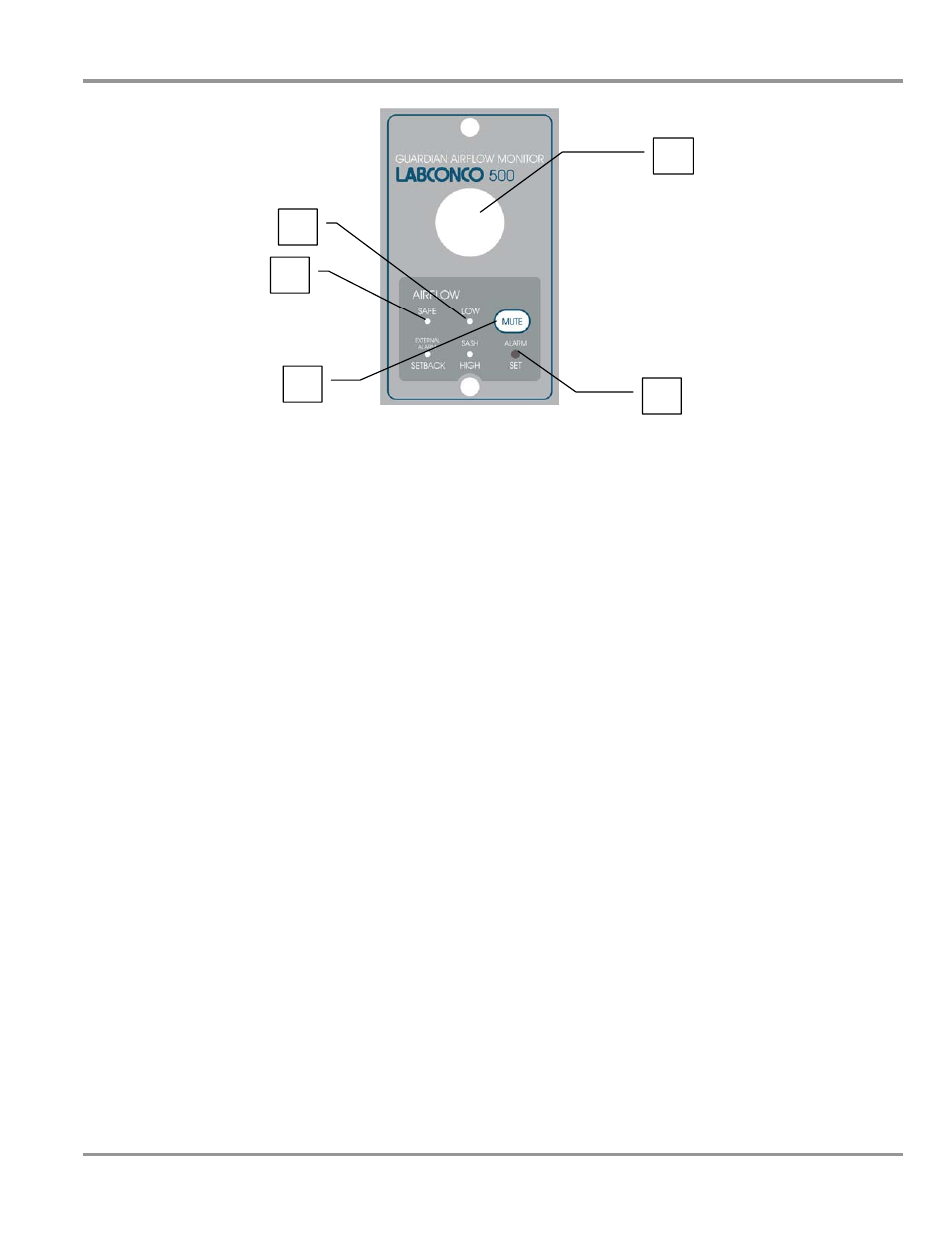
Figure 6-1
Component Identification