Operation modes – Lab.gruppen LAB 1600 User Manual
Page 7
8. Impedance matching (MLS-switch)
The MLS switch is located on the rear panel
with a LED indicator showing then the switch is
depressed and in the 2 ohms position. The MLS (
Minimum load select ) switch offer a impedance
matching, so you can drive the LAB 1600 in 2
ohms without increased heat losses. The chart
below shows the possible combinations:
LAB 1600 MLS switch
MLS Position
Speaker Impedance
4 ohms
2 ohms
8 ohms Stereo
430 W
220 W
4 ohms Stereo
840 W
430 W
2 ohms Stereo
1540 W*
870 W
8 ohms Bridged mono
1680 W
870 W
4 ohms Bridged mono
3000 W*
1740 W
Power rating at 1 kHz and 1% THD
* Not recomended selection, thermal protection may occur at high continous power.
Table 2.
The way to find the best MLS
TM
position for your application is by experimentation, the amplifier is very well
protected (even down to 0.3 ohms), but where speed is of essence stick to the fixed positions.
Operation modes
1. Stereo
operation
For stereo (dual channel ) operation, leave the Link
and Phase reverse switches in the undepressed
position. In this mode, both channels operate
independently of each other, with their level
attenuators controlling their respective levels.
Never connect either output terminal to ground
or in parallel. The recommended minimum
nominal impedance, for stereo or tandem operation,
is 2 ohms per channel.
2.
Tandem mono
For tandem ( dual channel-single input) operation ,
depress the Link switch. Both channels can now be
driven by a signal, at either input connector. The
output connection is the same as in stereo mode.
You can use either TRS connectors for linking out
etc. Do not use the remaining XLR and TRS
connectors for mixing or other purposes. Both
level attenuators are active, allowing you to set
different levels for each channel.
Never connect either output terminal to ground
or in parallel.
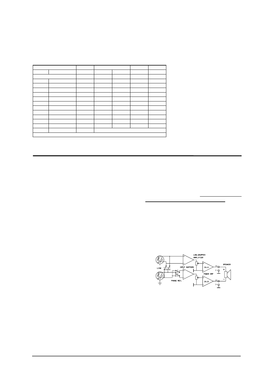
3.
Bridged mono
To bridge the amplifier, depress the Link switch (6)
and Phase reverse switch (5). Both channels are then
driven by a single signal at either input. You can
use any remaining input connectors for linking etc.
Do not use the remaining XLR and TRS as input
jacks simultaneously for mixing or other purposes.
To obtain an output, connect the speaker leads to pin
+1 on channel A Speakon to speaker positive
terminal and pin +1 on channel B Speakon to
speaker negative terminal . Do not connect either
of the -1 (negative) pins of the Speakons. Do not
connect speakers to channel A or B in the normal
manner in bridge mode, as this can cause serious
damage.
The recommended minimum nominal impedance
for bridged mono is 4 ohms (equivalent to driving
both channels at 2 ohms).
Driving bridged loads of less than 4 ohms may cause
a thermal overload.
Figure 10. Bridge mono connection
Both level attenuators must be at the same position.
We recommend you to put them in the 0 dB (full)
position.
7