Introduction, Unpacking, Front panel – Lab.gruppen iP 450 User Manual
Page 5: Q= fkqolar`qflk, Qkn= rей~евбец, Qko= cêçåí=m~åéä
Q= fkqolar`qflk=
Thank you for purchasing a Lab.gruppen power amplifier. This manual contains important information
on operating your amplifier correctly and safely. Please take some time and read this manual to
familiarize you with the advanced features of this amplifier.
QKN= rей~ЕвбеЦ=
Carefully open the shipping carton and check for any noticeable damage. Every Lab.gruppen amplifier
is tested and inspected before leaving the factory and should arrive in perfect condition. If found to be
damaged, notify the shipping company immediately. Only the consignee may institute a claim with the
carrier for damage incurred during shipping. Be sure to save the carton and packing materials for the
carrier's inspection.
It is also advisable to save the carton and packing material, even if the amplifier is undamaged. Should
you ever need to ship the amplifier, always use the original packing.
QKO= cêçåí=m~åÉä=
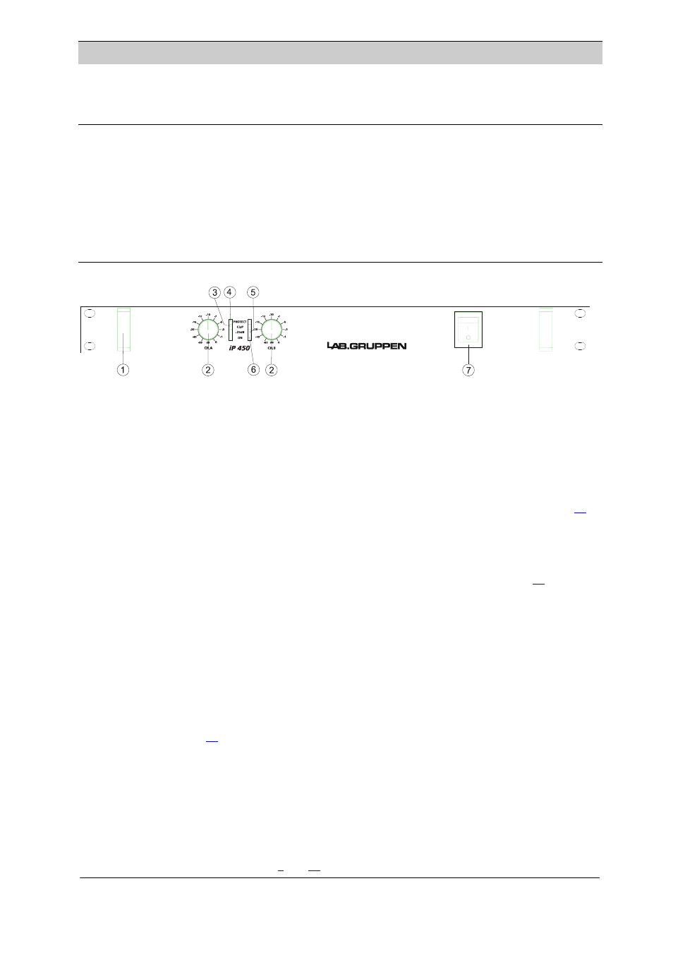
Figure 1 front panel
1. Carry/protection handle
Both handles can be used to carry the amplifier; they also act as protection for the front panel. In fixed
installations or where rack front covers are too shallow, they may be removed by unscrewing the
retaining bolts behind the front panel.
2. Input level attenuators
These controls are used to alter the signal level entering the amplifier. They are calibrated in dB to assist
the setup of active loudspeaker systems or cut down unwanted noise from the input signal. (See page
3. Clip/limit indicator
This indicator signals when the amplifier output is clipping or limiting. It has two different indication
states:
If the clip limiter is engaged, it has a short time constant and it illuminates briefly. (See page
).
If the clip limiter is not engaged, it has an increased time constant and it illuminates for a longer period.
4. Protect indicator
This indicator illuminates if the amplifier tries to operate above its maximum operating temperature
(90°
°
C). The indicator first comes on as a warning to either turn down the input level or check the
cooling arrangements. Beyond the maximum temperature the amplifier will mute the input signal. Once
the air have brought the output-amplifier heat-sinks back to normal operating temperature the input
signal is un-muted.
This indicator also illuminates when signals above 12 kHz are continuously present at full power at the
output terminals. If this occurs the input signal is muted, and the process cycles until the VHF signal is no
longer present. (See page
).
5. Signal present indicator.
Illuminates at –25dB below full output signal
6. On indicator
The two bottom green ”ON” LEDs indicate that the output circuits are receiving the correct rail voltage.
7. Power switch
Turns mains power on or off. (See page
and
)
i~ÄKÖêìééÉå== =
=
=
=
=
========================
Q
rëÉê=j~ем~д===бm=QRM======sÉêëáçå=MKP========OMMPJMOJOR=