LA Audio GCX20 User Manual
Page 17
Page 17
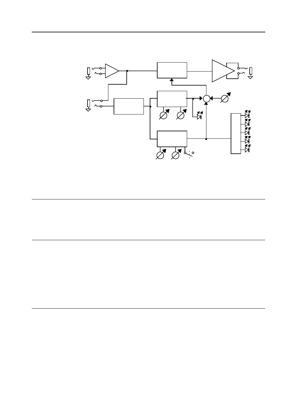
6.0 CIRCUIT DESCRIPTION
Threshold Ratio
Sidechain
insert
Audio
input
Gain
Auto
Vc
VCA
Audio
output
Gain reduction
meter
RMS
Detector
Compressor
Sidechain
Threshold Release
+
Gate
Gate
Sidechain
Fig: 6.0.1 Block diagram of the LA GCX20 showing the main signal paths
6.1 AUDIO
PATH
The input signal first passes through the electronically balanced input
stages and then directly to the VCA (Voltage Controlled Amplifier). The
signal then passes to the Ground Sensing output section.
6.2 SIDE
CHAIN
The input signal is also fed to the RMS detector via the Side Chain insert
connector. The RMS detector produces a DC voltage level proportional to
the RMS value of the incoming signal. This voltage feeds both the Gate
and Compressor side chains.
The level of signal leaving the VCA is controlled by the sum of the Gate
and Compressor sidechains and the GAIN control.
6.3 GATE
THRESHOLD
The Gate Threshold control adjusts the reference level for the gate. This
reference is compared with the RMS voltage and used to trigger a fast
acting switch. When the incoming signal exceeds the Threshold level this
switch closes, rapidly discharging the timing capacitor (Gate opens) and
remains on whilst the input signal is above Threshold.
RELEASE
When the input signal falls below Threshold the switch opens and allows
the timing capacitor to charge via the RELEASE control (Gate closes).