Hts-ss intallation manual 6-7, Hts-ss, 4gz telemetry product installation guide – HITEC Telemetry System User Manual
Page 3
Indoor lighting and outdoor lighting variations can affect the readings of the optic sensor.
Note
Each magnet has a X mark to identify polarity, please make sure the X mark to be faced out.
Otherwise the sensor cannot detect the magnet.
Note
The edit function as described at the end of this document in the HPP-22 data display. To use the Magnetic
sensor with heli main gear / head speed ratios
Note
4. Temperature Sensor
5. RPM Sensor
6
7
2.4Gz Telemetry Product Installation Guide
2.4Gz Telemetry Product Installation Guide
HTS-SS
HTS-SS
5. RPM Sensor
e. To customize the name of the temp sensor,
press
Temp-1
, then the
Rename
icon.
f. Use the keyboard to rename the sensor to
reflect its purpose. Repeat this process for the
other temp sensors used.
g. To view the
minimum, average and
maximum
temp readings for any of your
installed temp sensors, note the numbers
when any one of the sensors is selected on
the screen.
h. Exit this screen using the door icon in the
upper left of the screen.
i. To view all the sensor data in real time,
press Cockpit
There are two different RPM sensors available for use on the Hitec telemetry system.
1. Optical RPM Sensor (HTS-ORPM) - provides RPM information using a optic sensor. This is used for outdoor heli head speed
and prop plane RPM values.
2. Magnetic RPM Sensor (HTS-MRPM) - provides RPM information using a magnetic sensor. This is used for aircraft with
propellers, ducted fans, heli tail rotors and main gears.
There are two slots in the Sensor Station for RPM sensors. Any combination of optical or magnetic sensors can be used.
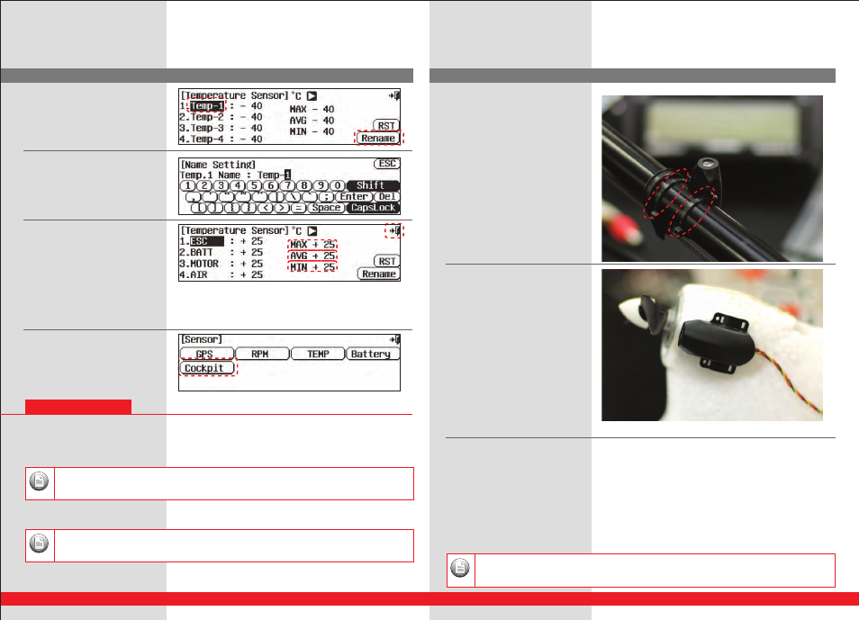
Optic Sensor Installation
A. For heli applications, note the shaped case
of the sensor. Install around the tail boom of
your heli using the supplied
zip ties.
Point it
straight up at the rotor disk avoiding any fly
bar paddles that will skew the results.
B. For prop driven aircraft, use double sided
tape to attach
the sensor in the airfame with the front of the
sensor aimed at the revolving propeller.
Magnetic Sensor Installation
A. The magnetic sensor consists of two main parts, the sensor and magnet. Three small magnets are supplied with the unit.
B. The typical installation will have the sensor mounted on the motor mount or airframe, and one magnet attached to the
spinner backing plate or prop hub in such a way as to “trigger” a signal every time the rotating magnet passes in front of the
stationary sensor.
C. It is suggested a small hole be drilled in the spinner backing plate, or prop hub into which one of the magnets is set flush
using hobby CA.
D. Note the tolerances here are very tight, the distance between the sensor and spinning magnet need to be 1mm.