Made in philippines, Ix oo fkdu jh – HITEC Laser 6 FM User Manual
Page 3
LASER 4&6
4
www.hitecrcd.com
SYSTEM INTRODUCTION MANUAL
LASER
4&6
SYSTEM
INTRODUCTION
MANUAL
LASER
4&6
S
YSTEM
INTRODUCTION
MANUAL
LASER 4&6
5
E. Adjustable Travel Volume (A.T.V.)
- CH 1 & CH 2 for Laser 4&6, CH4 for only Laser 6.
- This function adjusts the servo overall travel on CH 1 and CH 2.
- The rate setting is adjustable from 30% to 110%.
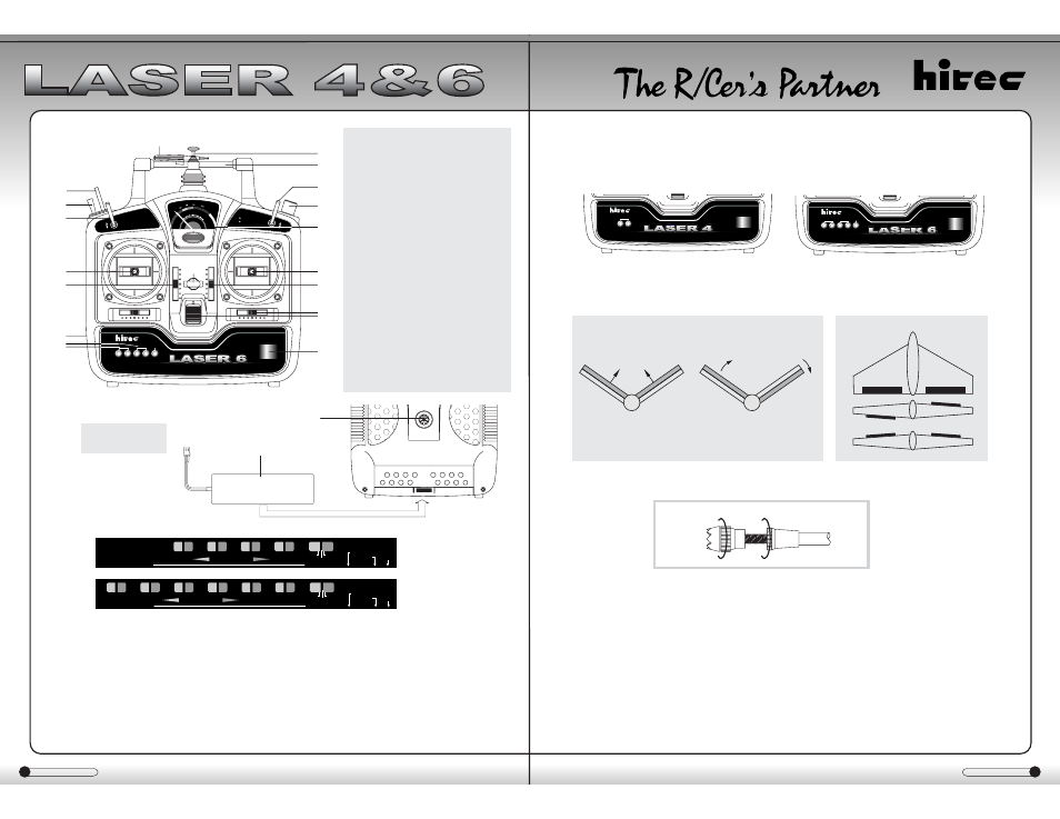
F. Mixing
- The Laser series transmitters are equipped with a switch that will mix ch.2 & ch.4
for V-tail aircraft or ch.1 and ch.2 for Elevon, or common flying wing type aircraft.
G. Control Stick Adjustment
- The length of the non-slip control sticks can be adjusted to suit the requirements of the user.
H. Stick Lever Tension Adjustment
- The unique open-stick assembly provides fully adjustable stick tension to adjust
the "feel" of the sticks in your hands.
- You may adjust the stick tension of your sticks to provide the "feel" that you like
for flying. To adjust your springs, you'll have to remove the rear case of the
transmitter. Using a screwdriver, remove the six screws that hold the
transmitter's rear cover into position, and put them in a safe place. Gently ease
off the transmitter's rear cover and move it to the right side of the transmitter,
carefully turning it as you would turn the page of a book. Now you'll see the view
shown in the illustration. Using a small Philips screwdriver, rotate the adjusting
screw for each stick for the desired spring tension. The tension increases when
the adjusting screw is turned clockwise, and decreases for counterclockwise
motion. When you are satisfied with the spring tensions, you may close the transmitter.
Very carefully reinstall the rear cover. When the cover is properly in place, tighten the six screws.
C. Specifications
- Power supply : 9.6V (8 cell) Nicad battery or 12V 8cell Dry battery
- Current drain : 150mA
- Output power : 500mw
- Modulation : PPM (FM)
D. Servo Reversing
- The Laser 4/6 FM transmitter is equipped with servo reversing on all channels.
- Leaving the switch in the middle will cause the radio to work erratically so please
make sure the switches are all pushed to the furthest end.
Layout (LASER 6 front)
Made in Philippines
ATV
CH1
CH2
Digital Proportional FM Radio Control System
FM
Layout (LASER 4&6 back)
Layout (LASER 4&6 bottom)
1.Trainer Jack
2.Nicad-battery
1
Made in Philippines
ATV
EPA
ATV
AIL
ELEV
THRO
RUDD
FM
Digital Proportional FM Radio Control System
2
1. Aileron/Elevator stick in MODE II
2. Throttle/Rudder stick in MODE II
3. Aileron trim
4. Elevator trim
5. Throttle trim
6. Rudder trim
7. Landing gear switch
8. Flap variable switch
9. Trainer ON-OFF switch
10. Voltage meter
11. Power switch
12. Rod antenna
13. Neck-strap connector
14. Recharge Jack
15. Crystal
16. Handle
17. Aileron & elevator and rudder
adjustable travel volume(A.T.V)
18. Throttle end point adjustment
high & low(E.P.A)
19. Screw Driver
20.Aileron & dual rate S/W
21.Elevator dual rate S/W
RII
QRU
UHY
Y0WDLO
HOHYRQ
QLFDG#SDFN
GU\#SDFN
[0WDO
VWRUDJH
FK7
FK6
FK5
FK4
PL[LQJ
VHUYR#UHYHUVH
RII
QRU
UHY
Y0WDLO
HOHYRQ
QLFDG#SDFN
GU\#SDFN
[0WDO
VWRUDJH
FK9
FK8
FK7
FK6
FK5
FK4
PL[LQJ
VHUYR#UHYHUVH
LASER 4
LASER 6
CH2
CH4
CH2
CH4
Up Elevator
Left Rudder (view from rear)
V-Tail MIXING
Elevon MIXING
CH1
CH2
Aileron Operation
Elevator Operation
A
B
Made in Philippines
ATV
EPA
ATV
AIL
ELEV
THRO
RUDD
FM
Digital Proportional FM Radio Control System
ELEV
D/R
AIL
D/R
V-tail Mixing
Elevon Mixing
1
10
2
5
14
18
17
19
16
12
8
20
7
21
9
13
4
3
11
15
Ix
oo
Fkdu
jh