Pinout assignments 50, Appendix, Module a module b – Hatteland Display HT B22 (Fanless) User Manual
Page 50
Pinout Assignments
50
IND100241-21
Appendix
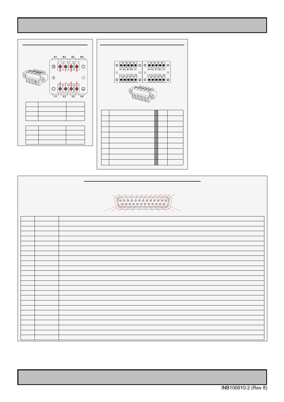
25-pin Female Parallel LPT, Bi-Directional, ECP/EPP Port Module
Type Number “HT 00272 OPT-A1”
13 12 11 10 9 8 7 6 5 4 3 2 1
25 24 23 22 21 20 19 18 17 16 15 14
Pin 01 STROBE
This signal indicates to the printer that data at PD7..0 are valid.
Pin 02 DATA0
Parallel data bus from PC board to printer. The data line are able to operate in PS/2 compatible bi-directional mode.
Pin 03 DATA1
Same as Pin 02
Pin 04 DATA2
Same as Pin 02
Pin 05 DATA3
Same as Pin 02
Pin 06 DATA4
Same as Pin 02
Pin 07 DATA5
Same as Pin 02
Pin 08 DATA6
Same as Pin 02
Pin 09 DATA7
Same as Pin 02
Pin 10 ACK
Signal from printer indicating that the printer has received the data and is ready to accept further data.
Pin 11 BUSY
Signal from printer indicating that the printer cannot accept further data.
Pin 12 PE
Signal from printer indicating that the printer is out of paper.
Pin 13 SELECT
Signal from printer to indicate that the printer is selected.
Pin 14 AUTO FEED This active low output causes the printer to add a line feed after each line printed.
Pin 15 ERR#
Signal from printer indicating that an error has been detected.
Pin 16 INIT#
This active low output initialises (resets) the printer.
Pin 17 SLIN#
Signal to select the printer sent from CPU board to printer.
Pin 18 GND
Ground
Pin 19 GND
Ground
Pin 20 GND
Ground
Pin 21 GND
Ground
Pin 22 GND
Ground
Pin 23 GND
Ground
Pin 24 GND
Ground
Pin 25 GND
Ground
10+10 pin Isolated Digital Input/Output Module
Type Number “HT00268 OPT-A1”
Module A Module B
Module A Module B
A1 External Power +
A1
IN+[0]
A2 N/C (Not Connected)
A2
IN-[0]
B1 External Power - (GND1)
B1
IN+[1]
B2 N/C (Not Connected)
B2
IN-[1]
O1 HS[0]
O1 N/C
C1 HS[1]
C1 IN+[2]
C2 N/C (Not Connected)
C2 IN-[2]
D1 HS[2]
D1 IN+[3]
D2 N/C (Not Connected)
D2 IN-[3]
O2 HS[3]
O2 N/C
4+4 pin CAN I/O Module, 2 channels
Type Number “HT 00254 OPT-A1”
X8
CAN1
X9
CAN2
1 2 3 4
1 2 3 4
Pin 01 X8 - Can1:
081 In Low
Pin 02 X8 - Can1:
082 Out Low
Pin 03 X8 - Can1:
083 In High
Pin 04 X8 - Can1:
084 Out High
Pin 01 X9 - Can2:
091 In Low
Pin 02 X9 - Can2:
092 Out Low
Pin 03 X9 - Can2:
093 In High
Pin 04 X9 - Can2:
094 Out High