Hanna Instruments BL 932700 User Manual
Page 2
REAR PANEL CONNECTIONS
Terminals #1, #2 and #3: Electrode
• Connect an ORP electrode to the meter BNC plug (#1).
• To benefit from the differential input, connect the proper
electrode wire (if available) or a cable with a potential
matching pin (grounding bar) to the relevant terminal
(#3) on the rear panel.
Note: When the Matching Pin can not be immersed together
with the electrode in the solution, disable the differential
input by shorting terminals #3 (Matching Pin) and
#2 (Electrode Reference) with a jumper wire.
Terminals #4: Dosing selection
• For Rdx dosage, leave the circuit open.
• For Oxd dosage, short the terminals with a jumper wire.
Terminals #5: 4-20 mA Output
• These output terminals are used for connecting a recorder.
The output is from 4 to 20 mA and is proportional to the
measured ORP value.
Terminals #6: Power Supply
• Model BL932700-0: connect the 2 wires of a 12 Vdc
power adapter to the terminals +12 Vdc and GND.
• Model BL932700-1: connect a 3-wire power cable to the
terminals while paying attention to the correct earth (PE),
line (L) and neutral (N1 for 115 V or N2 for 230 V) contacts.
Terminals #7: Dosing Contact
• This contact drives the dosing system, accordingly to the
selected setpoint and dosing direction:
• if “Rdx” dosage is set, the relay is ON and dosing
activated if measured value is higher than setpoint;
• if “Oxd” dosage is set, the relay is ON and dosing
activated if measured value is lower than setpoint.
Note: The setpoint has a typical hysteresis value comparable
to the meter accuracy.
Terminals #8: External Disabling Contact
• This is a normally open contact and can be used for
example for connecting a level controller.
• When the contact is closed, any dosing action stops, the
LED indicator on the front panel will blink Red and the
LCD will show the “HALT” warning message.
Note: If the OFF/Auto/ON switch is in ON position, the
dosing action will not stop, even if the external
disablig contact is closed. Dosage will proceed, the LED
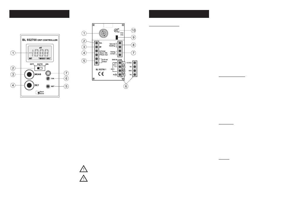
FUNCTIONAL DESCRIPTION
Front panel
Rear panel
1. Liquid Crystal Display
2. Switch for selecting dosing mode:
• OFF = dosing disabled
• Auto = automatic dosage, depending on setpoint value
and dosing selection
• ON = dosing always active
3. “MEAS” key to set the instrument to measurement mode
4. “SET” key to display and set the setpoint value
5. “SET” trimmer to adjust the setpoint value (within ±1000mV)
6. “CAL” trimmer
7. 3-colour LED indicator:
• Green = meter in measurement mode
• Orange/Yellow = dosing in progress
• Red, blinking = indicates an alarm condition
OPERATIONS
indicator will lit Orange/Yellow and the LCD will show
the “HALT” warning message.
Overtime system: jumper (#9) and trimmer (#10)
• This system allows the user to set a maximum dosing
period, by adjusting the rear trimmer from 5 (min) to
approx. 30 (max) minutes.
• When the set time is exceeded, any dosing action stops,
the LED indicator on the front panel will blink Red and the
LCD will show the “TIMEOUT” warning message. To exit
the overtime condition, set the OFF/Auto/ON switch to
“OFF” position, and then to “Auto” again.
• For disabling the overtime feature, simply remove the
jumper on the rear panel.
Note: The overtime system works only if the OFF/Auto/ON
switch is in “Auto” position.
OPERATING THE METER
Before proceeding make sure that:
• the setpoint value has been properly adjusted;
• all rear panel wiring and selections are correct;
• the Auto/OFF/ON switch is in the desired position.
Install or immerse the electrode in the solution to be moni-
tored, then press the “MEAS” key (if necessary).
The LCD will show the ORP (mV) value. The LED indicator will
light up Green when the meter is in measurement mode and
dosing is not active, while will light up Orange/Yellow for
signaling that a dosing action is in progress.
CALIBRATION
This meter is factory calibrated. Anyway, it is possible to check
the calibration as follows:
• ensure the meter is in measurement mode;
• immerse electrode and Matching Pin (if used) in one of the
available ORP test solutions (see “Accessories”);
• shake briefly and wait for reading to stabilize;
• if necessary, adjust reading through the “CAL” trimmer.
SETPOINT
Press the “SET” key: the display will show the default or
previously adjusted value, together with the “SET” indication.
Using a small screwdriver adjust the “SET” trimmer until the
desired setpoint value is displayed.
After 1 minute the meter automatically returns to the normal
mode; or press the “MEAS” key.
ISTBL2700R2 04/05
All external cables connected to the rear panel
should end with cable lugs.
A circuit breaker (rated 6A max.) must be
connected in close proximity to the equip-
ment, and in a position easy to reach by the
operator, for disconnection of the instrument
and of all the devices connected to the relays.
1. BNC plug for ORP electrode
2. Connection for electrode reference
3. Connection for potential Matching Pin
4. Rdx/Oxd dosage selection terminal:
• contact open = reductant selection
• contact closed = oxidant selection
5. 4-20 mA output terminal for recorder connection
6. Power supply terminal:
• for BL932700-0 model: 12 Vdc adapter
• for BL932700-1 model: 115 Vac or 230 Vac option
7. This contact acts as a switch for driving the dosing system (e.g.
dosing pump)
8. External control and disabling of dosing system
9. Jumper for enabling (jumper in) or disabling (jumper
removed) the overtime control
10. Trimmer for overtime setting (typically from 5 to 30 minutes)