Venting installation instructions – Desa DVF36TCR User Manual
Page 13
www.desatech.com
112108-01C
13
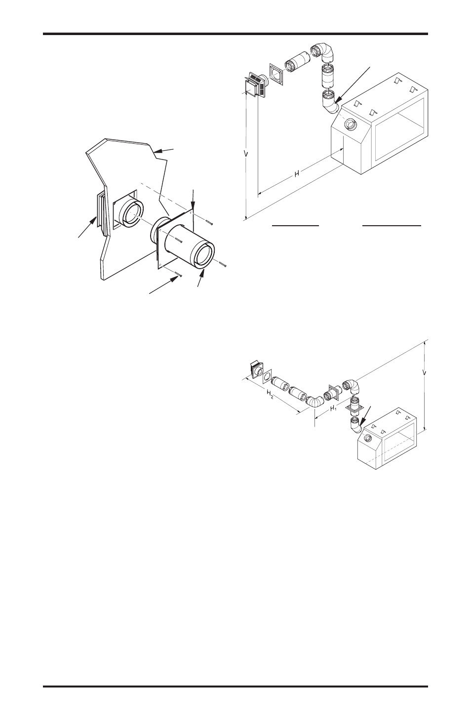
Vent Cap
(Horizontal
Termination)
Interior Wall
Surface
Wall
Firestop
Horizontal
Vent Pipe
Figure 18 - Connecting Vent Cap with
Horizontal Vent Pipe
Screw
VENTING INSTALLATION
INSTRUCTIONS
Continued
5.
Combustible Exterior Wall Only:
Slide
interior wall firestop over vent pipe before
connecting horizontal run to vent cap (see
Figure 18).
Horizontal Termination Configurations
Figures 19 and 20 show different configurations for
venting with horizontal termination. Each figure
includes a chart with vertical minimum/maximum
and horizontal maximum dimensions which must
be met. All connections must be sealed with
high temperature silicone sealant as specified in
the second warning statement on page 11. All
horizontal terminations require 1/4" rise per 12"
of horizontal run. You must add 1/4" of vertical
height (V) in the following tables for each foot of
horizontal run (H).
Figure 19 - Horizontal Termination
Configuration for Rigid Venting Using
One 90° Elbow
Horizontal Venting
Vertical (V)
Horizontal (H)
49.5" min.*
1" max.*
60" min.
" max.
2" min.
101" max.
84" min.
125" max.
132" min.
149" max.
(45° elbow, 1' vertical pipe, 90° elbow)
45° Starter
Elbow
Venting with Two 90° Elbows
Vertical (V)
Horizontal (H1) +
Horizontal (H2)
5' min.
4' max.
6' min.
8' max.
' min.
10' max.
8' min.
15' max.
20' max.
20' max.
Figure 20 - Horizontal Termination
Configuration for Rigid Venting Using
Two 90° Elbows with Termination at 90°
with Fireplace
45° Starter
Elbow